|
|
Topic: P212 |
I/O Module Configuration |
|
|
|
Topic: P212 |
I/O Module Configuration |
|
This topic describes the configuration of the types of Input and Output modules for your Productivity system:
Productivity Advanced Motion Control modules are also available for your Productivity system. The configuration of the PS-AMC modules is covered in the AMC Hardware Configuration topic.
Each Module has various Configuration parameters that may differ from system to system. To view and edit these parameters, double-click the Module within the Hardware Configuration window as shown below.
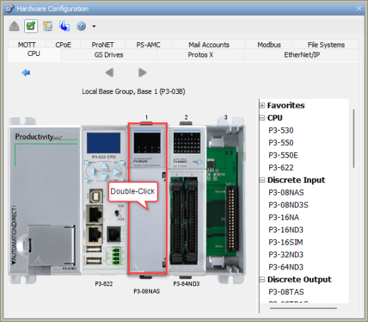
Note: The Hardware Component dialogs automatically appear when you are manually configuring your Base Groups.
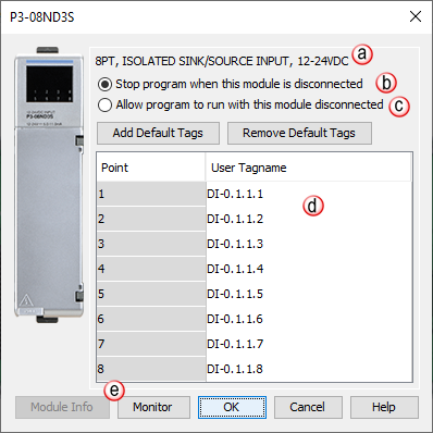
When you double-click on any of the Discrete I/O Modules, the respective Module's Configuration window will open. For example, if you double-click on the P3-08ND3S Module, the P3-08ND3S Configuration window shown below will open. Details about Configuring the Discrete I/O Modules are discussed below.
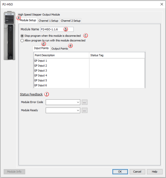
When you double-click on any High-Speed Input/Output Module from the Hardware Configuration window, the respective Module's Configuration window will open.
The following section discusses the configuration and options available with the High-Speed Output Module.
Note: The Input Points are not updated in STOP mode.
Registers: Enter a tag to view the count for each register within the Programmable Limit Switch (PLS) instruction (read-only).
Note: If an error message is present due to a fault, once the fault is corrected, a power cycle or a triggering of an SPOS instruction will clear the error.
|
Error Bit |
Error |
Description |
|
1 |
Missing External Power |
This module requires that external power be supplied in order to operate. If there is a loss of the supplied power, this bit will turn ON and all of the front panel fault LEDs will blink. |
|
2 |
Overload/Short Circuit Output 1 |
Each of the module outputs has built-in ESCP (Electronic Short Circuit Protection). This bit indicates a fault has occurred with Output 1. If a move was in progress, the Move Status Bit 12“Aborted-IO Fault”will be set for that particular move instruction. See the specific move instruction topic for the error bits associated with it. |
|
3 |
Overload/Short Circuit Output 2 |
Each of the module outputs has built-in ESCP (Electronic Short Circuit Protection). This bit indicates a fault has occurred with Output 2. If a move was in progress, the Move Status Bit 12“Aborted-IO Fault”will be set for that particular move instruction. See the specific move instruction topic for the error bits associated with it. |
|
4 |
Overload/Short Circuit Output 3 |
Each of the module outputs has built-in ESCP (Electronic Short Circuit Protection). This bit indicates a fault has occurred with Output 3. If a move was in progress, the Move Status Bit 12“Aborted-IO Fault”will be set for that particular move instruction. See the specific move instruction topic for the error bits associated with it. |
|
5 |
Overload/Short Circuit Output 4 |
Each of the module outputs has built-in ESCP (Electronic Short Circuit Protection). This bit indicates a fault has occurred with Output 4. If a move was in progress, the Move Status Bit 12“Aborted-IO Fault”will be set for that particular move instruction. See the specific move instruction topic for the error bits associated with it. |
|
6 |
Overload/Short Circuit Output 5 |
Each of the module outputs has built-in ESCP (Electronic Short Circuit Protection). This bit indicates a fault has occurred with Output 5. If a move was in progress, the Move Status Bit 12“Aborted-IO Fault”will be set for that particular move instruction. See the specific move instruction topic for the error bits associated with it. |
|
7 |
Overload/Short Circuit Output 6 |
Each of the module outputs has built-in ESCP (Electronic Short Circuit Protection). This bit indicates a fault has occurred with Output 6. If a move was in progress, the Move Status Bit 12“Aborted-IO Fault”will be set for that particular move instruction. See the specific move instruction topic for the error bits associated with it. |
|
8 |
Firmware Image CRC Error |
Module Firmware is faulted. |
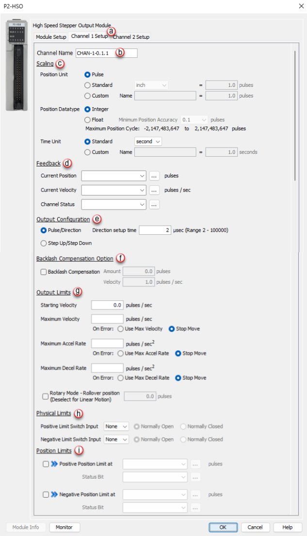
- Position Unit: Pulse: This option uses the raw Pulse per position unit selection.
- Position Unit: Standard: This option configures the numbers of pulses per unit. There are five pre-defined labels that can be selected: inch, foot, mm, degree and revolution. The pulses can also be specified in fractional increments (.1).
Once the scaling factor has been configured, the ladder logic can specify the target values to the HSO in the units that make sense for the application. For example: If a scaling value of 10 was configured and the ladder logic specified a target value of 10, the HSO would physically output 100 pulses.- Position Unit: Custom:This option also configures the number of pulses per unit but allows for a custom label to be entered. The pulses can also be specified in fractional increments (.1).
Once the scaling factor has been configured, the ladder logic can specify the target values to the HSO in the units that make sense for the application. For example: If a scaling value of 10 was configured and the ladder logic specified a target value of 10, the HSO would physically output 100 pulses.- Position Datatype: The position may be specified in terms of Integer or Float. Integer will provide a greater range but may be difficult to use when using the Scaling function. Conversely, Float will provide greater resolution in some cases but will greatly limit the range. The more resolution specified, the lower the range. It may be beneficial to scale the signal first then change the Position Datatype if needed to achieve the desired resolution and/or range. See the Understanding Maximum Position Cycle and Minimum Position Accuracy topic for more information.
- Time Unit: Standard: Choose the appropriate Time unit which will be used for this channel's time base. The three choices available are: second, minute and hour.
- Time Unit: Custom: A custom number of seconds can be configured in this field. The number of seconds can be entered in fractional increments (.1).
- Current Position Feedback: Insert a tag into this field in order to reference the channel’s current Pulse Count. The value will be represented in the scaled units specified from the Channel Scaling setup.
- Current Velocity Feedback: Insert a tag into this field in order to reference the channel’s current Velocity. The value will be represented in the scaled units specified from the Channel Scaling setup.
- Current Status: Insert a tag into this field in order to reference the current Status of the channel. A list of the possible Channel Status codes are listed below:
Status Bit
Status
Description
1
Px-HSO Only:Last Direction Backlash Positive
These bits indicate the last direction of travel. They are updated as soon as channel movement starts. If Backlash has been configured then these bits will not change state until after backlash has been “taken up” in the opposite direction.
2
Px-HSO Only:Last Direction Backlash Negative
3
Future
Future
4
Future
Future
5
Future
Future
6
Future
Future
7
Future
Future
8
Future
Future
9
Positive Limit Switch Tripped
These limit switches are configured and operate independently of each other. They are enabled individually allowing you to have just a positive, just a negative, or both limits. Each Limit Switch is only detected in its direction of travel. So an active Negative Limit will not prevent movement in the Positive Direction (and vice-versa). This allows a channel to “back off” of a Limit Switch in the opposite direction. But this also means that the Limit Switches will not protect from an axis traveling in the wrong direction. Note 1: If both Limit Switches are configured to the same Input then you will not be able to “back off” of the limit, manual interaction would be required, this type of setup is usually called “over-travel limit”. Note 2: The relevant instruction's Move Status Bit 10 “Aborted – Hit Limit” is also set at the same time.
10
Negative Limit Switch Tripped
11
Future
Future
12
Future
Future
13
Px-HSO Only:Positive Position Limit Tripped
These bits indicate when the channel's current position violates the Position Limit setup in the H/W Configuration. Position Limits allow the axis movement to be restricted without physical limit switches. The Position Limits are configured and also operate independently of each other. They are enabled individually allowing you to have just a positive, just a negative, or both limits. Note 1:The relevant instruction's Move Status Bit 10 “Aborted – Hit Limit” is also set at the same time. Note 2: These limits can be changed on the fly during a move. Note 3: Position Limits are ignored during HOME instructions since the Home position of the Channel has not been matched to a physical Axis position.
14
Px-HSO Only: Negative Position Limit Tripped
15
Registration Stop Tripped
When an instruction is configured for Registration and the Decel to a Stop option is selected, this bit will turn ON after the channel comes to a stop. Also the relevant instruction's Move Status Bit 8 “Stopped at Registration Target” will be set.
16
Module Error - See Module Error Code (above)
This bit indicates that an error exists in the Module Error Code, look there for further information.
Status Bits 17-32 are used only by the PS-AMCx Modules
(not used by the legacy Px-HSO and PxHSI modules)17
Info- Encoder is a Master
The encoder is an active Master of a drivetrain
18
Info- Axis is a Master
This axis ( not the encoder ) is an active Master of a drivetrain
19
Info- Axis is a Slave
This axis is an active Slave in a drivetrain
20
Info- Axis is Enabled
When configured with “Axis requires Enable”, this is HI when AEN is active.
21
Info- Position Deviation Exceeded
If configured, this will be HI if the difference between the Encoder position and the commanded position is greater than the configured deviation window.
22
Info- Capture Input Previously Defined
MREG Only: The define position capture input/edge has already been defined for capture.
23
Future
Future
24
Aborted- Drive Not Ready
When configured with “Axis Uses Drive Ready”, the target axis is not providing a ready state signal on IN1- Drv Rdy
25
Aborted- Axis at Limit At Start
Axis is on the limit sensor at the start of a move in that direction
26
Aborted- Axis Not Enabled
When configured with “Axis Requires Enable”, this is HI when the AEN instruction is not active and a move on this axis is trying to start or during the move
27
Aborted- Position Deviation Stop
When configured, the axis was stopped due to the difference between the Encoder position and the commanded being greater than the configured deviation window.
28
Aborted- Axis is a Drivetrain Slave
Axis cannot be used by another instruction because it is an active Slave to another Master axis.
29
Aborted- Axis is Linear
Axis is configured as a Linear axis when it is required to be Rotary Axis
30
Aborted- Slave Exceeded Maximum Velocity
Axis is an active Slave and was commanded to go faster than maximum allowable configured velocity of the axis. This usually is because the gear ratio is too high
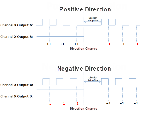
- Pulse/Direction: This selection configures the module to generate the Pulse Train on Output A of the channel and the Direction is established on Output B of the channel. When the logic tells the module to change direction, Output B will toggle from low to high and vice versa. The Direction Setup Time field specifies how long the direction signal should be established before the pulse train starts. The range is from 2 microseconds to 100 milliseconds. If the module is currently sending a pulse train and a direction change has been issued, the module will freeze the pulse outputs for the time period specified.
- Step Up/Step Down: When this option is selected, the Pulse Train is generated on Output A when a Positive direction has been specified and on Output B when a Negative direction has been specified.
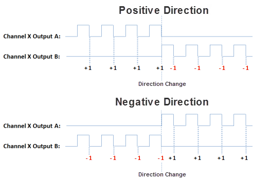
- Quadrature: When this option is selected, the Pulse Train output is generated on Output A and Output B, offset by a 1/2 cycle. Direction changes from the logic cause the offset to change from one output to the other. There are also Direction Polarity options that allow the polarity to be changed logically.
- Direction Polarity: The Direction Polarity setting determines the initial sequence of the Pulse offsets or Direction Line level. Refer to the Pulse Train Output Configuration diagrams above to see how this setting affects the initial Pulse output sequence.
- Starting Velocity (Pulses/sec): The velocity to start at when accelerating to higher target velocities. This is typically set to the maximum rate the motor can instantaneously achieve from a stopped state. The system must be able to withstand the jerk created by this immediate velocity change. Using this feature can reduce acceleration/deceleration times, and therefore reduce process cycle times. For target velocities below the Starting Velocity, there is no acceleration/deceleration, and the profile will start and stop at the target rate without ramping.
- Maximum Velocity (Pulses/sec): This is the maximum Pulse rate that the module will output. The On Error selections specify how the module should behave when the maximum rate is exceeded. The module can be configured to maintain the maximum rate or to Stop the move if a pulse rate higher than the maximum is specified by the logic.
- Maximum Accel Rate (Pulses/sec2): This is the maximum Acceleration rate that the module will output. The On Error selections specify how the module should behave when the maximum rate is exceeded. The module can be configured to maintain the maximum rate or to Stop the move if an acceleration rate higher than the maximum is specified by the logic.
- Maximum Decel Rate (Pulses/sec2): This is the maximum Deceleration rate that the module will output. The On Error selections specify how the module should behave when the maximum rate is exceeded. The module can be configured to maintain the maximum rate or to Stop the move if a deceleration rate higher than the maximum is specified by the logic.
- Rotary Mode - Rollover Position: If selected, when the count reaches the specified rollover position, the next positive pulse will reset the count to 0. Also, if the count is at 0, the next negative pulse will reset the count (roll under) to the specified rollover position. The value is specified in user units but the final scaled value must be within 1 and 2,147,483,647 whole counts. If the final scaled roll over position value is not a multiple of whole pulses, the fractional pulse amount will be ignored. When this feature is used, the count will always be a positive number between 0 and the rollover position.
- Positive Limit Switch Input: This option will stop the module pulse output if the specified Limit Switch becomes true when encountered in the Positive direction. An error will be indicated in the Module Error Code tag when this occurs. Motion in the negative direction is permitted in this state to allow for movement away from the limit switch unless the same switch is used for both positive and negative limits.
- Negative Limit Switch Input: This option will stop the module pulse output if the specified Limit Switch becomes true when encountered in the Negative direction. An error will be indicated in the Module Error Code tag when this occurs. Motion in the positive direction is permitted in this state to allow for movement away from the limit switch unless the same switch is used for both positive and negative limits.
- Enable Positive Position Limit at: This option will stop the module pulse output (unless performing a Homing routine) if the module reaches the count specified (constant or Tag value) while traveling in the Positive direction. An error will be indicated in the Status Bit specified when this occurs. As with the hardware switch limits, movement is allowed in the negative direction in order to move away from the limit switch. The "On the fly" symbol
indicates that this value can be changed while the instruction is running.
- Enable Negative Position Limit at: This option will stop the module pulse output (unless performing a Homing routine) if the module reaches the count specified (constant or Tag value) while traveling in the Negative direction. An error will be indicated in the Status Bit specified when this occurs. As with the hardware switch limits, movement is allowed in the positive direction in order to move away from the limit switch. The "On the fly" symbol
The following section discusses the configuration and options available with the High-Speed Input Module.
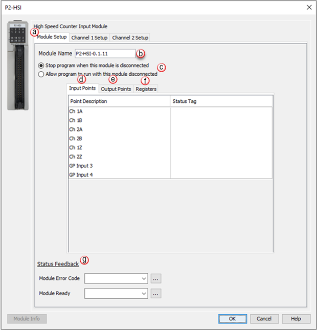
Input Points: There are two general purpose Inputs available which can be used to trigger events in the Registration instruction or used with the Inhibit Count on Input option of the module’s channel I/O configuration. Tagnames need to be assigned to these Inputs in order to be referenced from within the ladder logic. By default, inputs 1-6 are used for channel inputs but internal tags may be assigned to each point for the purpose of monitoring from within the ladder code.
Note: The Input Points are not updated in STOP mode.
Registers: Enter a tag to view the count for each register within the Programmable Limit Switch (PLS) instruction (read-only).
Status Feedback: A tagname must be entered in the Module Error Code field in order to reference any current Errors in the module from within the ladder logic. The table below describes the Errors possible. The Module Ready field accepts boolean tags and is used to indicate that the module is installed, configured and ready for instructions. This option must be used in combination with the Hot Swap feature to ensure instructions will execute as intended.
Note: If an error message is present due to a fault, once the fault is corrected, a power cycle or a triggering of an SPOS instruction will clear the error.
|
Error Bit |
Error |
Description |
|
1 |
Missing External Power |
This module's outputs require that external power be supplied in order to operate. If there is a loss of the supplied power, this bit will turn ON and all of the front panel fault LEDs will blink. |
|
2 |
Overload/Short Circuit Output 1 |
Each of the module outputs has built-in ESCP (Electronic Short Circuit Protection). This bit indicates a fault has occurred with Output 1. |
|
3 |
Overload/Short Circuit Output 2 |
Each of the module outputs has built-in ESCP (Electronic Short Circuit Protection). This bit indicates a fault has occurred with Output 2. |
|
4 |
Overload/Short Circuit Output 3 |
Each of the module outputs has built-in ESCP (Electronic Short Circuit Protection). This bit indicates a fault has occurred with Output 3. |
|
5 |
Overload/Short Circuit Output 4 |
Each of the module outputs has built-in ESCP (Electronic Short Circuit Protection). This bit indicates a fault has occurred with Output 4. |
|
6 |
Future |
Future |
|
7 |
Future |
Future |
|
8 |
Firmware Image CRC Error |
Module Firmware is faulted. |
|
9 |
Channel 1 - Quadrature Sequence Fault |
A valid Quadrature signal should only have one edge at any point in time. Either the rising or falling edge of Channel A or Channel B, but not both. If the module detects that both Channel A and Channel B change states at the same time then this error bit will be set. This may indicate a bad encoder or noise on the channel. |
|
10 |
Future |
Future |
|
11 |
Future |
Future |
|
12 |
Future |
Future |
|
13 |
Channel 2 - Quadrature Sequence Fault |
A valid Quadrature signal should only have one edge at any point in time. Either the rising or falling edge of Channel A or Channel B, but not both. If the module detects that both Channel A and Channel B change states at the same time then this error bit will be set. This may indicate a bad encoder or noise on the channel. |
|
14 |
Future |
Future |
|
15 |
Future |
Future |
|
16 |
Future |
Future |
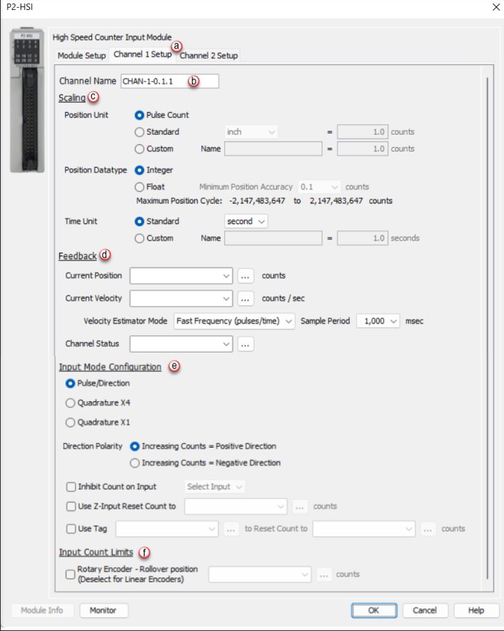
- Position Unit: Pulse: This option uses the raw Pulse per unit selection.
- Position Unit: Standard: This option configures the numbers of pulses per unit. There are five pre-defined labels that can be selected: inch, foot, mm, degree and revolution. The pulses can also be specified in fractional increments (.1).
- Position Unit: Custom: This option also configures the number of pulses per unit but allows for a custom label to be entered. The pulses can also be specified in fractional increments (.1).
- Position Datatype: The position may be specified in terms of Integer or Float. Integer will provide a greater range but may be difficult to use when using the Scaling function. Conversely, Float will provide greater resolution in some cases but will greatly limit the range. The more resolution specified, the lower the range. See the Understanding Maximum Position Cycle and Minimum Position Accuracy topic for more information.
- Time Unit: Standard: Choose the appropriate Time unit which will be used for this channel's time base. The three choices available are: second, minute and hour.
- Time Unit: Custom: A custom number of seconds can be configured in this field. The number of seconds can be entered in fractional increments (.1).
Note: The Channel Feedback tags are not updated in STOP mode.
- Current Position Feedback: Insert a tag into this field in order to reference the channel’s current High-Speed Count. The value will be represented in the scaled units specified from the Channel Scaling setup.
- Current Velocity Feedback: Insert a tag into this field in order to reference the channel’s current Velocity. The value will be represented in the scaled units specified from the Channel Scaling setup.
- Velocity Estimator Mode: This selection is used in determining how the Current Velocity will be calculated.
- Fast Frequency (pulses/time): This mode requires the user to select a sample period specific to their process. A shorter sample period will have less resolution. Recommended for velocities of 1khz and above. Calculations are done based on the number of events that occur within the sample period. Fast Frequency is the most accurate mode when the sample period is long. The update rate of the velocity calculations for this mode is directly proportional to the sample period.
Velocity Fast Freq = # of Pulses / Sample Period
(Note: The Sample Period must be between 1 and 0.001 second.)
Example:
- Slow Frequency (time/pulse): Slow Frequency at low velocities (under 1khz) will provide a more accurate and faster update rate than Fast Frequency. Calculations are based on the amount of time that passes between two pulses. As frequency increases, Slow Frequency loses accuracy as the resolution between pulses decreases.
Velocity Slow Freq = 1 / Time between Pulses
Example:
- Autosense: Autosense combines the features of Slow and Fast Frequency Modes to provide a velocity calculation. Autosense uses the velocity from Slow Frequency to calculate a sample period to be used in Fast Frequency calculation. This provides rolling adjustment through all frequency ranges. This mode works in all ranges, so it is the easiest to implement, but sacrifices accuracy due to the combined limitations of Slow and Fast Frequency Modes.
Velocity Autosense = # of Pulses / Autosense Sample Period
Where: Autosense Sample Period = (1 / Velocity Slow Freq) x 100
Note: Autosense Sample Period max / min values are 1 and 0.001 second respectively. The initial sample period will be 2 seconds and then dynamically adjust based on the input frequency.
Example:
- Sample Period: Used in conjunction with Fast Frequency Mode. Sets the period of time that the pulses will be sampled in order to determine the velocity rate.
- Channel Status: Insert a tag into this field in order to reference the current Status of the channel. A list of the possible Channel Status codes are listed below:
Status Bit
Status
1
Alert – Current Position Out of Range of New Cycle” . If in Rotary Mode, if the rollover to set to a position that is less than the current position. When this occurs, the old (currently running) rollover position will be active until the condition is corrected by either hanging the rollover value to be greater than the current position OR change the current position to be less than the proposed new rollover position.
2
Future
3
Future
4
Future
5
Future
6
Inhibited - Reset Tag out of range1 This occurs when the tag or constant value used to store the position that will be set when the Set Position tag becomes true and has value that is outside of the Rollover Position when Rotary Mode is enabled.
Note: The channel will be inhibited at all times that the value of the tag or constant is outside of the rollover range AND the Set Tag (Boolean) is TRUE . To clear this condition, change the position value to be within the rollover range or disable the Use Tag to Set Position feature.
7
Inhibited - Z Reset out of range1 This occurs when the tag or constant value used to store the position that will be set when the Z input point is triggered has a value that is outside of the Rollover Position when Rotary Mode is enabled.
Note: The channel will be inhibited at all times that the value of the tag or constant is outside of the rollover range regardless if the input is triggered or not. To clear this condition, change the position value to be within the rollover range or disable the Z Reset feature.
8
Inhibited - Rotary Rollover out of range1 This occurs when Rotary Mode is enabled AND the Rollover position is <= 0 OR is outside the Channel position range (i.e. larger than 8.3M when float scaling is selected). To clear this condition, change the rollover position value to greater than 0 AND be within the channel position range.
9
Alert - Position Rolled Over2
10
Alert - Position Rolled Under2
11
Future
12
Future
13
Future
14
Future
15
Future
16
Module Error - See Module Error Code (above)
Note 1: These can only occur when in Rotary Mode, if not in Rotary Mode then any value is valid.
Note 2: These report the occurrence of a Roll Over and/or Roll Under. They will remain set for 3 scans and then clear. This makes it possible to detect multiple rollover and/or rollunder events using ladder code.
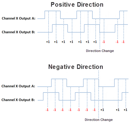
- Pulse/Direction: This selection configures the module to receive the Pulse Train on Input A of the channel and to read the Direction on Input B of the channel. When the signal on Input B is low, the module will count up when receiving pulses on Input A. Conversely, when the signal on Input B is high, the module will count down when receiving pulses on Input A.
- Quadrature X1: With this selection, the channel count will depend on which input is leading and which is trailing. If the Direction Polarity is set to Increasing Counts = Positive Direction and Input A is leading Input B by a 1/2 pulse, then the count will increase by one with every rising edge of the pulse received on Input A.
- Quadrature X4: As with the Quadrature X1 setting, the channel count is dependent upon which input is leading and which is trailing. With the Quadrature X4 selection however, the counts will increment on each rising and falling edge of both input pulse trains.
- Direction Polarity: This selection determines the direction polarity of the incoming signals.
- Increasing Counts = Positive Direction: With Pulse/Direction mode, if the signal on Input B is low, pulses on Input A will generate an increasing count. When the signal on Input B is high, pulses on Input A will generate a decreasing count.
With Quadrature mode, if the signal on Input A leads the signal on Input B, the count will increase. If the signal on Input B leads the signal on Input A the count will decrease.
- Increasing Counts = Negative Direction: With Pulse/Direction mode, if the signal on Input B is low, pulses on Input A will generate a decreasing count. When the signal on Input B is high, pulses on Input A will generate an increasing count.
With Quadrature mode, if the signal on Input A leads the signal on Input B, the count will decrease. If the signal on Input B leads the signal on Input A the count will increase.
- Inhibit Count on Input: Enabling this selection allows the user to specify an input that will be used to inhibit the count. The count will be inhibited when this specific input is in its active state. Valid inputs for this feature are: 1Z, 2Z, as well as, General Purpose (GP) Inputs 3 and 4.
- Use Z-Input Reset Count to: Enabling this feature will cause the count to reset to the specified count value when the Z Input for the channel goes to the active state. This value is specified in user units but the final scaled value must be within -2,147,483,647 and 2,147,483,647 whole counts. If the final scaled reset count value is not a multiple of whole pulses, the fractional pulse amount will be ignored.
- Use Tag... to Reset Count to: When the specified tag equals 1, the count for the channel will be reset to the specified count value. This value is specified in user units but the final scaled value must be within -2,147,483,647 and 2,147,483,647 whole counts. If the final scaled reset count value is not a multiple of whole pulses, the fractional pulse amount will be ignored.
- Rotary Encoder - Rollover Position: When the count reaches the specified rollover position, the next positive pulse will reset the count to 0. When the count is at 0, the next negative pulse will reset the count (roll under) to the specified rollover position. The value is specified in user units but the final scaled value must be within 1 and 2,147,483,647 whole counts. If the final scaled roll over position value is not a multiple of whole pulses, the fractional pulse amount will be ignored. When this feature is used, the count will always be a positive number between 0 and your rollover number.
When you double-click on any of the Analog I/O Modules, the respective Module's Configuration window will open. For example, if you double-click on the P3-08AD Module, the P3-08AD Configuration window shown below will open. Details about Configuring the Analog I/O Modules are discussed below.
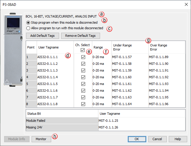
Note: P Series RTD Modules must have All Channels configured to the same Range.
Note: The P3-04ADS does not allow for Signal Range selection in the software configuration. Signal Type is determined when wiring the field device.
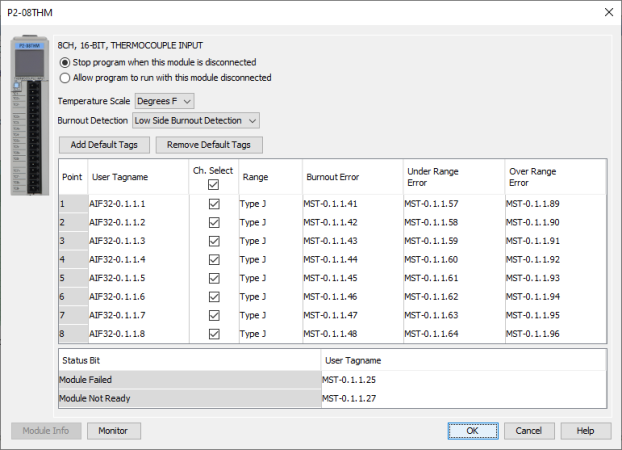
For all P Series temperature analog modules (NTC, RTD,and THM) there is a user selectable Burnout Detection setting that can be set to either Low Side Burnout Detection or High Side Burnout Detection. This setting determines the value that will be loaded into the channel's tag name when a sensor for that specific channel detects a failure or becomes disconnected.
Values that get loaded depend on what setting is selected:
- Discrete I/O points:
DI = Discrete Input Point
DO = Discrete Output Point
- Boolean data items other than I/O points
MST = Module Status (Examples: Blown fuse or out of range error bits)
- Analog points. These use five digits. The first two digits designate the type of point and the last three describe the data type used.
--> AIxxx = Analog Input Point
--> AOxxx = Analog Output Point
--> xxF32 = Floating Point 32 Bit data type
--> xxS32 = Signed 32 Bit data type
B is the Base Group number. The LocalBase Group with the CPU is Group0.
C is the Base number. The Base with the CPU or P3-RS/P3-RX is Base1.
D is the Slot number. The Slot to the right of the CPU is Slot1.
E is the Item number.
- If the Tag Name is for an I/O module, this digit will be the point number.
- If the Tag Name is for a Status indication, this digit will differentiate them.
Example:P3-16TR has two fuses (one on each common) and a blown fuse indicator bit for each. Their default Tag Names are MST-x.x.x.1 and MST-x.x.x.2. MST-x.x.x.1 is the blown fuse indicator for the fuse on the common of channels 1 through 8.
Note: The P3-530 and P1-540 CPU only supports local I/O.
User Tag Names are created by Users in the Tag Database. The following rules apply to Tag Names created by Users:


