Topic: P303

P1-PWM

Description

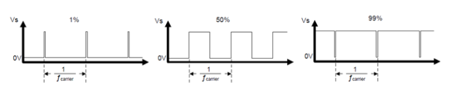
A Pulse Width Modulation (PWM) Signal is a method for generating an analog signal using a digital source. A PWM signal consists of two main components that define its behavior: a duty cycle and a frequency. The duty cycle describes the amount of time the signal is in a high (on) state as a percentage of the total time of it takes to complete one cycle. The frequency determines how fast the PWM completes a cycle (i.e. 1000 Hz would be 1000 cycles per second), and therefore how fast it switches between high and low states. By cycling a digital signal off and on at a fast enough rate, and with a certain duty cycle, the output will appear to behave like a constant voltage analog signal when providing power to devices.


  1. Duty Cycle: When the signal is high, we call this "on time". To describe the amount of "on time", we use the concept of duty cycle. Duty cycle is measured in percentage. The percentage duty cycle specifically describes the percentage of time a digital signal is on over an interval or period of time. This period is the inverse of the frequency of the waveform.

    If a digital signal spends half of the time on and the other half off, we would say the digital signal has a duty cycle of 50% and resembles an ideal square wave. If the percentage is higher than 50%, the digital signal spends more time in the high state than the low state, and vice versa if the duty cycle is less than 50%. Here is a graph that illustrates these three scenarios:

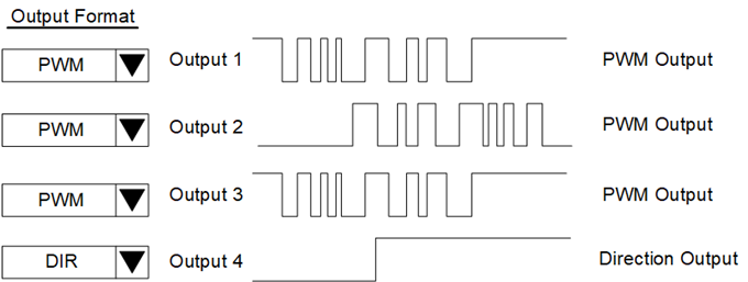
Note: Invert the signal by simply using the sinking outputs or use a MATH instruction to produce it in ladder such as DCINVERTED=100-DCCOMMAND.

  1. Carrier Frequency: Defines the base frequency of the square wave output (PWM mode only).
  2. Output Type: The output format of each output in the module can be configured to be either a PWM waveform output or a Direction (DIR) output. When configured to be PWM outputs, the outputs will be controlled in duty cycle and carrier frequency using the system tags assigned. When configured as DIR, the output will be a direction output where the duty cycle tag is set to zero or non-zero values to change the output to LO and HI respectively. The value of the carrier frequency tag will be ignored in the module on outputs configured as DIR.

  3. Duty Cycle Implied Decimal: User selection for fixed point number of digits. Applied only to the duty cycle percentage (%).

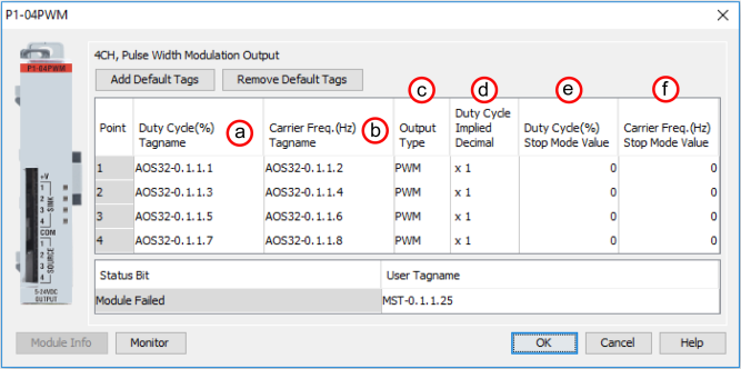
Selection /

Data Range

Notes

x 1

* - Duty Cycle Range 0 -> 100

x 0.1

* - Duty Cycle Range 0 -> 1000

x 0.01

* - Duty Cycle Range 0 -> 10000


  1. Duty Cycle Stop Mode Value: This is the value written to the duty cycle when the CPU goes into Stop Mode.

Note: Raw, unscaled value. Does not consider Implied Decimal.

  1. Carrier Frequency Stop Mode Value: This is the value written to the Carrier Frequency when the CPU goes into Stop Mode.