|
|
Topic: P300 |
High Speed Input |
|
|
|
Topic: P300 |
High Speed Input |
|
The following section discusses the configuration and options available with the High-Speed Input Module.
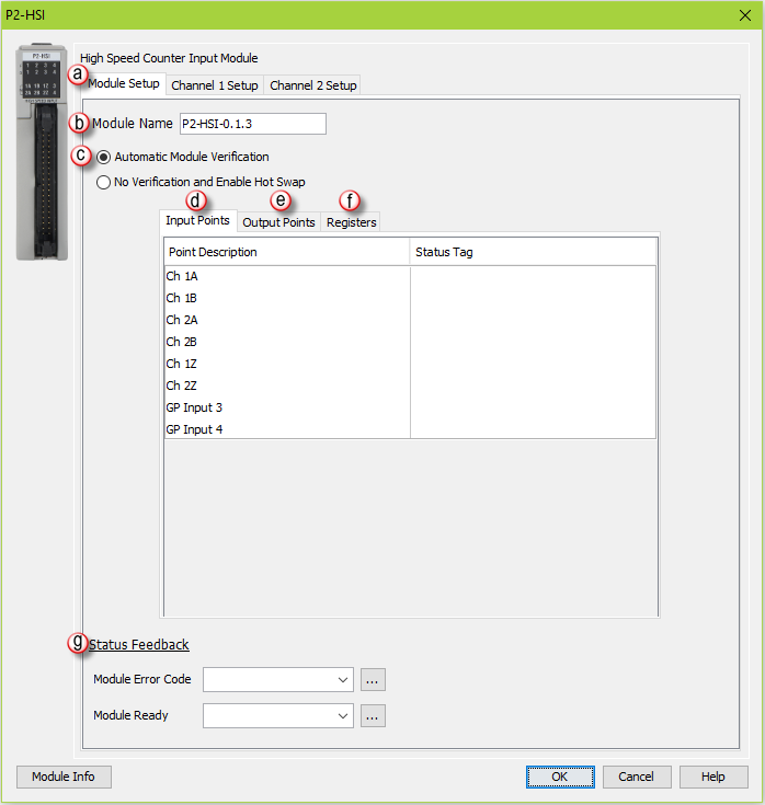
Input Points: There are two general purpose Inputs available which can be used to trigger events in the Registration instruction or used with the Inhibit Count on Input option of the module’s channel I/O configuration. Tagnames need to be assigned to these Inputs in order to be referenced from within the ladder logic. By default, inputs 1-6 are used for channel inputs but internal tags may be assigned to each point for the purpose of monitoring from within the ladder code.
Note: The Input Points are not updated in STOP mode.
Registers: Enter a tag to view the count for each register within the Programmable Limit Switch (PLS) instruction (read-only).
Status Feedback: A tagname must be entered in the Module Error Code field in order to reference any current Errors in the module from within the ladder logic. The table below describes the Errors possible. The Module Ready field accepts boolean tags and is used to indicate that the module is installed, configured and ready for instructions. This option must be used in combination with the Hot Swap feature to ensure instructions will execute as intended.
Note: If an error message is present due to a fault, once the fault is corrected, a power cycle or a triggering of an SPOS instruction will clear the error.
|
Error Bit |
Error |
Description |
|
1 |
Missing External Power |
This module's outputs require that external power be supplied in order to operate. If there is a loss of the supplied power, this bit will turn ON and all of the front panel fault LEDs will blink. |
|
2 |
Overload/Short Circuit Output 1 |
Each of the module outputs has built-in ESCP (Electronic Short Circuit Protection). This bit indicates a fault has occurred with Output 1. |
|
3 |
Overload/Short Circuit Output 2 |
Each of the module outputs has built-in ESCP (Electronic Short Circuit Protection). This bit indicates a fault has occurred with Output 2. |
|
4 |
Overload/Short Circuit Output 3 |
Each of the module outputs has built-in ESCP (Electronic Short Circuit Protection). This bit indicates a fault has occurred with Output 3. |
|
5 |
Overload/Short Circuit Output 4 |
Each of the module outputs has built-in ESCP (Electronic Short Circuit Protection). This bit indicates a fault has occurred with Output 4. |
|
6 |
Future |
Future |
|
7 |
Future |
Future |
|
8 |
Firmware Image CRC Error |
Module Firmware is faulted. |
|
9 |
Channel 1 - Quadrature Sequence Fault |
A valid Quadrature signal should only have one edge at any point in time. Either the rising or falling edge of Channel A or Channel B, but not both. If the module detects that both Channel A and Channel B change states at the same time then this error bit will be set. This may indicate a bad encoder or noise on the channel. |
|
10 |
Future |
Future |
|
11 |
Future |
Future |
|
12 |
Future |
Future |
|
13 |
Channel 2 - Quadrature Sequence Fault |
A valid Quadrature signal should only have one edge at any point in time. Either the rising or falling edge of Channel A or Channel B, but not both. If the module detects that both Channel A and Channel B change states at the same time then this error bit will be set. This may indicate a bad encoder or noise on the channel. |
|
14 |
Future |
Future |
|
15 |
Future |
Future |
|
16 |
Future |
Future |
- Position Unit: Pulse: This option uses the raw Pulse per unit selection.
- Position Unit: Standard: This option configures the numbers of pulses per unit. There are five pre-defined labels that can be selected: inch, foot, mm, degree and revolution. The pulses can also be specified in fractional increments (.1).
- Position Unit: Custom: This option also configures the number of pulses per unit but allows for a custom label to be entered. The pulses can also be specified in fractional increments (.1).
- Position Datatype: The position may be specified in terms of Integer or Float. Integer will provide a greater range but may be difficult to use when using the Scaling function. Conversely, Float will provide greater resolution in some cases but will greatly limit the range. The more resolution specified, the lower the range. See the Understanding Maximum Position Cycle and Minimum Position Accuracy topic for more information.
- Time Unit: Standard: Choose the appropriate Time unit which will be used for this channel's time base. The three choices available are: second, minute and hour.
- Time Unit: Custom: A custom number of seconds can be configured in this field. The number of seconds can be entered in fractional increments (.1).
Note: The Channel Feedback tags are not updated in STOP mode.
- Current Position Feedback: Insert a tag into this field in order to reference the channel’s current High-Speed Count. The value will be represented in the scaled units specified from the Channel Scaling setup.
- Current Velocity Feedback: Insert a tag into this field in order to reference the channel’s current Velocity. The value will be represented in the scaled units specified from the Channel Scaling setup.
- Velocity Estimator Mode: This selection is used in determining how the Current Velocity will be calculated.
- Fast Frequency (pulses/time): This mode requires the user to select a sample period specific to their process. A shorter sample period will have less resolution. Recommended for velocities of 1khz and above. Calculations are done based on the number of events that occur within the sample period. Fast Frequency is the most accurate mode when the sample period is long. The update rate of the velocity calculations for this mode is directly proportional to the sample period.
Velocity Fast Freq = # of Pulses / Sample Period
(Note: The Sample Period must be between 1 and 0.001 second.)
Example:
- Slow Frequency (time/pulse): Slow Frequency at low velocities (under 1kHz) will provide a more accurate and faster update rate than Fast Frequency. Calculations are based on the amount of time that passes between two pulses. As frequency increases, Slow Frequency loses accuracy as the resolution between pulses decreases.
Velocity Slow Freq = 1 / Time between Pulses
Example:
- Autosense: Autosense combines the features of Slow and Fast Frequency Modes to provide a velocity calculation. Autosense uses the velocity from Slow Frequency to calculate a sample period to be used in Fast Frequency calculation. This provides rolling adjustment through all frequency ranges. This mode works in all ranges, so it is the easiest to implement, but sacrifices accuracy due to the combined limitations of Slow and Fast Frequency Modes.
Velocity Autosense = # of Pulses / Autosense Sample Period
Where: Autosense Sample Period = (1 / Velocity Slow Freq) x 100
(Note: Autosense Sample Period max / min values are 1 and 0.001 second respectively. The initial sample period will be 2 seconds and then dynamically adjust based on the input frequency.)
Example:
- Sample Period: Used in conjunction with Fast Frequency Mode. Sets the period of time that the pulses will be sampled in order to determine the velocity rate.
- Channel Status: Insert a tag into this field in order to reference the current Status of the channel. A list of the possible Channel Status codes are listed below:
Status Bit
Status
1
Alert – Current Position Out of Range of New Cycle. If in Rotary Mode, if the rollover is set to a position that is less than the current position. When this occurs, the old (currently running) rollover position will be active until the condition is corrected by either changing the rollover value to be greater than the current position OR change the current position to be less than the proposed new rollover position.
2
Future
3
Future
4
Future
5
Future
6
Inhibited - Reset Tag out of range1 This occurs when the tag or constant value used to store the position that will be set when the Set Position tag becomes true and has value that is outside of the Rollover Position when Rotary Mode is enabled.
Note: The channel will be inhibited at all times that the value of the tag or constant is outside of the rollover range AND the Set Tag (Boolean) is TRUE . To clear this condition, change the position value to be within the rollover range or disable the Use Tag to Set Position feature.
7
Inhibited - Z Reset out of range1 This occurs when the tag or constant value used to store the position that will be set when the Z input point is triggered has a value that is outside of the Rollover Position when Rotary Mode is enabled.
Note: The channel will be inhibited at all times that the value of the tag or constant is outside of the rollover range regardless if the input is triggered or not. To clear this condition, change the position value to be within the rollover range or disable the Z Reset feature.
8
Inhibited - Rotary Rollover out of range1 This occurs when Rotary Mode is enabled AND the Rollover position is <= 0 OR is outside the Channel position range (i.e. larger than 8.3M when float scaling is selected). To clear this condition, change the rollover position value to greater than 0 AND be within the channel position range.
9
Alert - Position Rolled Over2
9
Alert - Position Rolled Under2
11
Future
12
Future
13
Future
14
Future
15
Future
16
Module Error - See Module Error Code (above)
Note 1: These can only occur when in Rotary Mode, if not in Rotary Mode then any value is valid.
Note 2: These report the occurrence of a Roll Over and/or Roll Under. They will remain set for 3 scans and then clear. This makes it possible to detect multiple rollover and/or rollunder events using ladder code.
- Pulse/Direction: This selection configures the module to receive the Pulse Train on Input A of the channel and to read the Direction on Input B of the channel. When the signal on Input B is low, the module will count up when receiving pulses on Input A. Conversely, when the signal on Input B is high, the module will count down when receiving pulses on Input A.
- Quadrature X1: With this selection, the channel count will depend on which input is leading and which is trailing. If the Direction Polarity is set to Increasing Counts = Positive Direction and Input A is leading Input B by a 1/2 pulse, then the count will increase by one with every rising edge of the pulse received on Input A.
- Quadrature X4: As with the Quadrature X1 setting, the channel count is dependent upon which input is leading and which is trailing. With the Quadrature X4 selection however, the counts will increment on each rising and falling edge of both input pulse trains.
- Direction Polarity: This selection determines the direction polarity of the incoming signals.
- Increasing Counts = Positive Direction: With Pulse/Direction mode, if the signal on Input B is low, pulses on Input A will generate an increasing count. When the signal on Input B is high, pulses on Input A will generate a decreasing count.
With Quadrature mode, if the signal on Input A leads the signal on Input B, the count will increase. If the signal on Input B leads the signal on Input A the count will decrease.
- Increasing Counts = Negative Direction: With Pulse/Direction mode, if the signal on Input B is low, pulses on Input A will generate a decreasing count. When the signal on Input B is high, pulses on Input A will generate an increasing count.
With Quadrature mode, if the signal on Input A leads the signal on Input B, the count will decrease. If the signal on Input B leads the signal on Input A the count will increase.
- Inhibit Count on Input: Enabling this selection allows the user to specify an input that will be used to inhibit the count. The count will be inhibited when this specific input is in its active state. Valid inputs for this feature are: 1Z, 2Z, as well as, General Purpose (GP) Inputs 3 and 4.
- Use Z-Input Reset Count to: Enabling this feature will cause the count to reset to the specified count value when the Z Input for the channel goes to the active state. This value is specified in user units but the final scaled value must be within -2,147,483,647 and 2,147,483,647 whole counts. If the final scaled reset count value is not a multiple of whole pulses, the fractional pulse amount will be ignored.
- Use Tag... to Reset Count to: When the specified tag equals 1, the count for the channel will be reset to the specified count value. This value is specified in user units but the final scaled value must be within -2,147,483,647 and 2,147,483,647 whole counts. If the final scaled reset count value is not a multiple of whole pulses, the fractional pulse amount will be ignored.
- Rotary Encoder - Rollover Position: When the count reaches the specified rollover position, the next positive pulse will reset the count to 0. When the count is at 0, the next negative pulse will reset the count (roll under) to the specified rollover position. The value is specified in user units but the final scaled value must be within 1 and 2,147,483,647 whole counts. If the final scaled roll over position value is not a multiple of whole pulses, the fractional pulse amount will be ignored. When this feature is used, the count will always be a positive number between 0 and your rollover number.


