|
|
Topic: P312 |
AMC Hardware Configuration |
|
|
|
Topic: P312 |
AMC Hardware Configuration |
|
You may find the following videos helpful in setting up the PS-AMC module(s):
The following section discusses the configuration and options available with the PS-AMC modules.
Note: All parameters are checked before the instruction becomes active. If a parameter violates one of the rules, the instruction will be aborted before any action occurs.
Note: When using an AMC with a SureServo2 drive in External Step/Direction mode, set the Z value (hundredths place digit) of the External Pulse Type P1.000 parameter to a value of 1. By default, the value of the parameter is 1042 and should be adjusted to 1142 to prevent possible missing step command pulses to the drive.
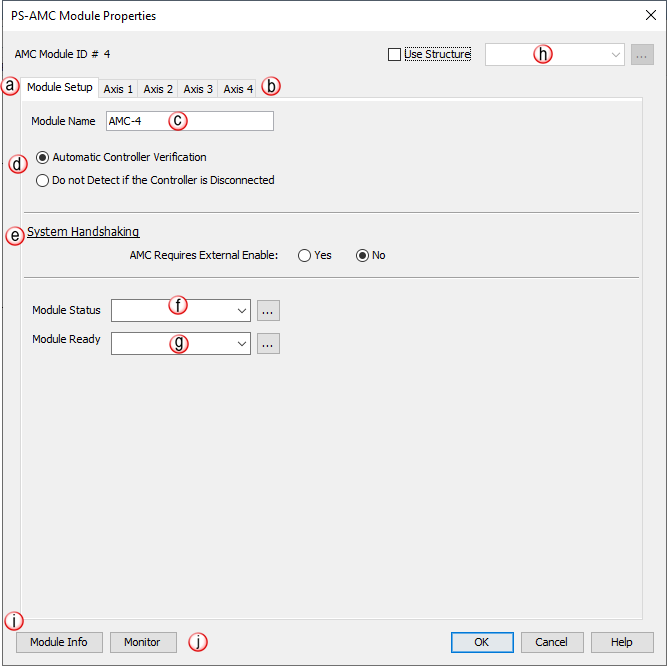
a. Module Setup: This tab provides the setup parameters of the selected AMC module. Each individual axis setup parameters are found on their respective tab.
b. Axis: Access to each Axis on the AMC module (Maximum 4 axes). See details in PS-AMC Module Properties box below.
c. Module Name: Each AMC module can be given a unique name (maximum 16 characters) for easier reference within the hardware configuration, instructions and throughout the programming software. It will be used to identify the specific AMC device and will be used to select it in all relevant instructions. The name MUST be unique among all AMC devices, HSO and HSI module names.
d. Automatic Controller Verification: Selected by default. Generates a critical error when an AMC Module is removed from the network causing a Hardware mismatch and forcing the CPU out of RUN mode. Select Do not Detect if the Controller is Disconnected if Hot Swap functionality is desired.
e. System Handshaking: Allows an outside device to enable and disable the entire controller. When Yes is selected, the MC EN input must be True in order for any motion to occur. Any active motion will terminate if this input goes False at any time.
f. Module Status: A tagname must be entered in the Module Status field in order to reference any current Errors in the module from within the ladder logic. The table below describes the Errors:
|
Bit Number |
Error |
Description |
|
1 |
Ext Enable Missing |
Alert - the module is configured to use Ext Enable and the input state is False |
|
2 |
Future |
|
|
3 |
Future |
|
|
4 |
Future |
|
|
5 |
Future |
|
|
6 |
Future |
|
|
7 |
Future |
|
|
8 |
Firmware Image CRC Error |
Controller Firmware is faulted |
g. Module Ready: The Module Ready field accepts Boolean tags and is used to indicate that the module is installed, configured and ready for instructions. This option must be used in combination with the Hot Swap feature to ensure instructions will execute as intended.
h. Use Structure: Entering a Tag Name here will create a related group of tags that will automatically populate each of the tags used in this module. Each of the names for those tags will use the string entered in this field as a prefix.
i. Module Info: When Productivity Suite is connected to the AMC module, information will be returned about the module such as Part Number, Hardware Revision and MAC ID.
j. Monitor: Adds all tags associated with this instruction to the Data View window
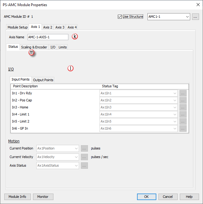
k. Axis Name: The selected axis this instruction will control. AMC modules have 1 or up to 4 axes depending on the model number.
l. Status Tab: Read only tags that provide status of Input & Output points:
I/O - Input Points: There are six discrete Inputs available that can be used to trigger events. Tag names must be assigned to these Inputs to be monitored in the ladder logic.
- In1 - Drv Rdy: Some motor drives will have a drive ready signal that can be monitored to allow the AMC know when it can send move commands. This is an optional input. By default, when no signal is connected, the AMC will treat the drive as ready.
- In2 - Pos Cap: This input is used to monitor a sensor or external signal that will trigger a position capture.
- In3 - Home: This input is used to monitor a sensor or external signal to trigger an event during homing operations.
- In4 - Limit 1: This input is used as a hard positive stop travel limit. When this input is sensed, motion in the positive velocity command is halted and can only resume in the negative direction.
- In5 - Limit 2: This input is used to as a hard negative stop travel limit. When this input is sensed, motion in the negative velocity command direction is halted and can only resume in the positive direction.
- In6 - GP In: This input can be used as a general purpose input or can be used as a Position Capture input when assigned.
I/O - Output Points:There are three discrete Outputs available. Tag names must be assigned to these Outputs to be monitored in the ladder logic.
- Out1 - GP Out: This output can be used as a general purpose output.
- Out2 - En: This output is used to Enable a connected device output if configured. Otherwise, it can be used as a General Purpose Output.
- Out3 - ATR: This output is used to signal Axis At Rest. When configured, it will be active when the axis is not being commanded to move . Otherwise, it can be used as a General Purpose Output.
Motion: These tags store the current status of the motion elements of the Axis:
- Current Position: Add a tag to this field to reference the channel’s current Pulse Count. The value will be represented in the scaled units specified on the Axis Scaling & Encoder setup tab.
- Current Velocity: Add a tag to this field to reference the channel’s current Velocity. The value will be represented in the scaled units specified from the Axis Scaling setup.
- Axis Status: Add a tag to this field to reference the current Status of the axis. The possible Axis Status codes are listed below:
|
Status Bit |
Status |
Description |
|
1 |
Px-HSO Only: Last Direction Backlash Positive |
These bits indicate the last direction of travel. They are updated as soon as channel movement starts. If Backlash has been configured then these bits will not change state until after backlash has been “taken up” in the opposite direction. |
|
2 |
Px-HSO Only: Last Direction Backlash Negative |
|
|
3 |
Future |
Future |
|
4 |
Future |
Future |
|
5 |
Future |
Future |
|
6 |
Future |
Future |
|
7 |
Future |
Future |
|
8 |
Future |
Future |
|
9 |
Positive Limit Switch Tripped |
These limit switches are configured and operate independently of each other. They are enabled individually allowing you to have just a positive, just a negative, or both limits. Each Limit Switch is only detected in its direction of travel. So an active Negative Limit will not prevent movement in the Positive Direction (and vice-versa). This allows a channel to “back off” of a Limit Switch in the opposite direction. But this also means that the Limit Switches will not protect from an axis traveling in the wrong direction. Note 1: If both Limit Switches are configured to the same Input then you will not be able to “back off” of the limit; manual interaction would be required. This type of setup is usually called “over-travel limit”. Note 2: The relevant instruction's Move Status Bit 10 “Aborted – Hit Limit” is also set at the same time. |
|
10 |
Negative Limit Switch Tripped |
|
|
11 |
Future |
Future |
|
12 |
Future |
Future |
|
13 |
Px-HSO Only: Positive Position Limit Tripped |
These bits indicate when the channel's current position violates the Position Limit setup in the H/W Configuration. Position Limits allow the axis movement to be restricted without physical limit switches. The Position Limits are configured and also operate independently of each other. They are enabled individually allowing you to have just a positive, just a negative, or both limits. Note 1:The relevant instruction's Move Status Bit 10 “Aborted – Hit Limit” is also set at the same time. Note 2: These limits can be changed on the fly during a move. Note 3: Position Limits are ignored during HOME instructions since the Home position of the Channel has not been matched to a physical Axis position. |
|
14 |
Px-HSO Only: Negative Position Limit Tripped |
|
|
15 |
Registration Stop Tripped |
When an instruction is configured for Registration and the Decel to a Stop option is selected, this bit will turn ON after the channel comes to a stop. Also the relevant instruction's Move Status Bit 8 “Stopped at Registration Target” will be set. |
|
16 |
Module Error - See Module Error Code (above) |
This bit indicates that an error exists in the Module Error Code; look there for further information. |
|
Status Bits 17-32 are used only by the PS-AMCx Modules
|
||
|
17 |
Info- Encoder is a Master |
The encoder is an active Master of a drivetrain. |
|
18 |
Info- Axis is a Master |
This axis ( not the encoder ) is an active Master of a drivetrain. |
|
19 |
Info- Axis is a Slave |
This axis is an active Slave in a drivetrain. |
|
20 |
Info- Axis is Enabled |
When configured with “Axis requires Enable”, this is HI when AEN is active. |
|
21 |
Info- Position Deviation Exceeded |
If configured, this will be HI if the difference between the Encoder position and the commanded position is greater than the configured deviation window. |
|
22 |
Info- Capture Input Previously Defined |
MREG Only: The define position capture input/edge has already been defined for capture. |
|
11 |
Future |
Future |
|
24 |
Aborted- Drive Not Ready |
When configured with “Axis Uses Drive Ready”, the target axis is not providing a ready state signal on IN1- Drv Rdy. |
|
25 |
Aborted- Axis at Limit At Start |
Axis is on the limit sensor at the start of a move in that direction. |
|
26 |
Aborted- Axis Not Enabled |
When configured with “Axis Requires Enable”, this is HI when the AEN instruction is not active and a move on this axis is trying to start or during the move. |
|
27 |
Aborted- Position Deviation Stop |
When configured, the axis was stopped due to the difference between the Encoder position and the commanded position being greater than the configured deviation window. |
|
28 |
Aborted- Axis is a Drivetrain Slave |
Axis cannot be used by another instruction because it is an active Slave to another Master axis. |
|
29 |
Aborted- Axis is Linear |
Axis is configured as a Linear axis when it is required to be Rotary Axis. |
|
30 |
Aborted- Slave Exceeded Maximum Velocity |
Axis is an active Slave and was commanded to go faster than maximum allowable configured velocity of the axis. This usually is because the gear ratio is too high. |
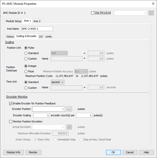
m. Scaling & Encoder Tab:
Allows use of Axis Scaling tool to configure Pulse Count, the Time Unit to Seconds, and choose a Position Data type. This scaling can then be used in the ladder code.
Axis Scaling
There are several scaling options for user code convenience. Since there are many different types of applications that the module may be used in, the provided scaling feature may not work for every scenario. In this case, set the Position Unit to Pulse, and the Time Unit (Standard) to Seconds, then use scaling in the ladder code. See the Scaling help topic for more details on this function.
Position Unit
Pulse: This option uses the raw Pulse per unit selection.
Standard: This option configures the numbers of pulses per unit. There are five pre-defined labels that can be selected: inch, foot, mm, degree and revolution. The pulses can also be specified in fractional increments.
Custom: This option also configures the number of pulses per unit but allows for a custom label to be entered. The pulses can also be specified in fractional increments.
Position Data Type
Integer: Integer will provide a greater range but may be difficult to use when using the Scaling function.
Float: Float will provide greater resolution in some cases but will greatly limit the range. The greater Maximum Position Accuracy specified, the lower the range. See the Understanding Maximum Position Cycle and Minimum Position Accuracy topic for more information.
Time Unit
Standard: Choose the appropriate Time Unit which will be used for this channel's time base. The three choices available are: second, minute and hour.
Custom: A custom number of seconds can be configured in this field. The number of seconds can be entered in fractional increments.
Note: By default, scaling is not used and positions are in raw pulses, speed is in pulses/sec, ramp is in pulses/sec2, and jerk in pulses/sec3.
Encoder Monitor
The Encoder Monitor option is used if the application calls for actual position to be set via an incremental encoder which allows the application to determine if any error occurred between the commanded position and the actual position.
Note: If this option is used, the commanded position will be set to this Encoder Position prior to the start of the move to zero the error.
The Encoder Scaling parameters allows the user set scaling for the incoming encoder signals so that accurate deviation checks can be made by the system. These values set the number of encoder counts per number of commanded pulses. For instance, if the output of the AMC commands the machine to move 10,000 pulses and the encoder feeds back 10,000 counts during the move, the values should be set to 1 encoder count per 1 pulse. However, the same move was completed but the connected encoder only sends back 5,000 counts, then the values should be set to 1 encoder count per 2 pulses. Conversely, if the encoder returns 20,000 counts for the same move, then the values should be set to 2 counts per 1 pulse.
Note: The Encoder Scaling first value is the number of encoder counts from the encoder not the number of lines in the encoder. For instance, a 100 line encoder will provide 400 counts to the AMC because of the quadrature signals.
Monitor Position Deviation
When enabled, the amount of position deviation is monitored by the system. The maximum amount of acceptable deviation is set (in raw pulses) and defines a window of -value -> value. When the actual deviation exceeds the window, the system will respond by the action selected.
The responses to choose from are:
- Warn Only which sets the Info-Position Deviation Exceeded status bit (status bit number 21) HIGH
- Immediate Stop which will IMMEDIATELY STOP any active move on the axis. It also sets the Aborted – Position Deviation Stop status bit (status bit number 27) HIGH and the Info-Position Deviation Exceeded status bit (status bit number 21) HIGH
- Stop at Max. Decel Rate which will STOP any active move on the axis ** and the output will decelerate to a stop at the rate defined by Maximum Decel Rate configured on the Limits tab. It also sets the Aborted – Position Deviation Stop status bit (status bit number 27) HIGH and the Info-Position Deviation Exceeded status bit (status bit number 21) HIGH.
** Important Note: Instructions that define and use a slave axis (i.e., GEAR, MREG, AREG, FCO) will stop immediately, NOT AT THE MAX DECEL RATE.
** Important Note: Encoder Monitor and Monitor Position Deviation are raw pulses and do not follow the Axis Scaling.
n. I/O Tab:
Configures settings for Drive Handshaking, Polarity Settings, and Reset Position By Input for the AMC module..
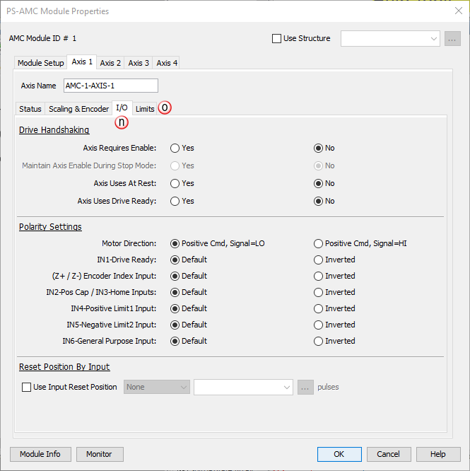
Drive Handshaking
AMC Axis Enable (AEN) instruction: Allows the user to define whether or not the Enable Output (OUT2) is required to be active before a move is commanded to the axis. If Yes is selected, the Enable instruction will be required to be active before a move can be started on that axis or any drivetrain including that axis. If No is selected, an AMC Axis Enable (AEN) instruction is not required for that axis.
Maintain Axis Enable During Stop Mode: When Yes, the Enable Output will remain at the last state during Stop Mode.
Axis Uses At Rest: Allows the user to define whether or not the At Rest Output is used for a given axis. If Yes is selected, the At Rest Output will operate automatically during the start and stop of a move. If No is selected, the At Rest Output will be available to use as a general purpose Output for that axis.
Axis Uses Drive Ready: Allows the user to define whether or not the Drive Ready Input (IN1) is used for a given axis. If Yes is selected, the Drive Ready signal will let the AMC know that the connected drive is ready to go. If using this handshake and Drive Ready goes LOW at any time during operation:
- motion commands will fault, if active,
- a command will not start, and
- a flag will be set in the Axis Status feedback tag.
If No is selected, the Drive Ready Input will be available for as a general purpose Input for that axis.
Polarity Settings
Motor Direction: The motor command direction can be inverted so a person can change the relative direction of rotation.
IN1-Drive Ready: Ready input is an indication to the AMC that the drive that is hooked up to the AMC is ready to be run. If the configuration for that axis is set such that the Drive Ready input is not needed, it can be used as a general purpose input.
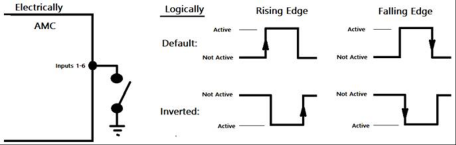
(Z+/Z-) Encoder Index Input: Input polarity is a bit more difficult to demonstrate. Basically, when default setting is when the differential signal is not active [Z+ signal is LO and Z- signal is HI]: see Default rising and Falling edges above. Inverted setting behaves like the Inverted logic above.
IN2- Pos Cap/ IN3 - Home Inputs: are multiplexed internally thus the single selection for both. IN2-Pos Cap is active anytime registration and external events are monitored EXCEPT during the execution of the HOME instruction, then IN3-Home is active.
IN4 - Positive Limit1 Input: is used as for the positive moving limit switch.
IN5 - Negative Limit2 Input: is used as for the negative moving limit switch.
IN6 - General Purpose Input: is the General Purpose input but can also be used to capture registration events when selected to do so.
Reset Position By Input: allows the user to define an input and edge that, when triggered, will reset the actual position of the axis to the position defined. If enabled, the user should define a position and then select one of the permitted inputs. If the axis is defined as rotary, then the position will be checked to make sure it will fit in the rotary cycle. The value of the reset position can be changed on-the-fly which means it is updated in the controller every scan.
Shown with AMC1, however all axes on all models behave the same way.
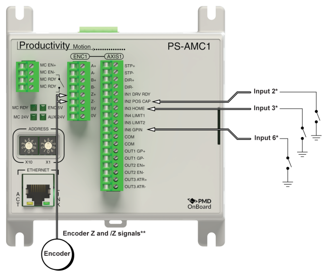
*Note 1: Input 2 and Input 3 are multiplexed inside the controller and share a high speed capture input. Only one can be used at a time. Input 2 is used generally for everything that is not a homing move and the HOME instruction will list Input 3 and not Input 2. It is ok to use the same sensor on both with a wire jumper.
**Note 2: nput 6 and Encoder Z index are multiplexed inside the controller and share a high speed capture input. Only one can be used at a time. Both Input 6 and the Z-Input can be used for a high speed capture or position reset. There is a caveat though. The high speed input they share is really the Z index (differential signals) and Input 6 was added in case the system has an NPN type sensor used for Position Reset: their behavior is identical. The capture interrupt only occurs in 1 of the 4 unique states of a quadrature decoded input.

Note: Input 6 will only fire the reset or capture event once every 4 quad counts whether or not an encoder is used. When an encoder is not used, the internal mechanism still uses the internal encoder loopback for positioning. If the axis is at stand still, there is only a 1 in 4 chance the event will fire so it should be used on an axis that is in motion. The Z input will fire only once per encoder revolution.
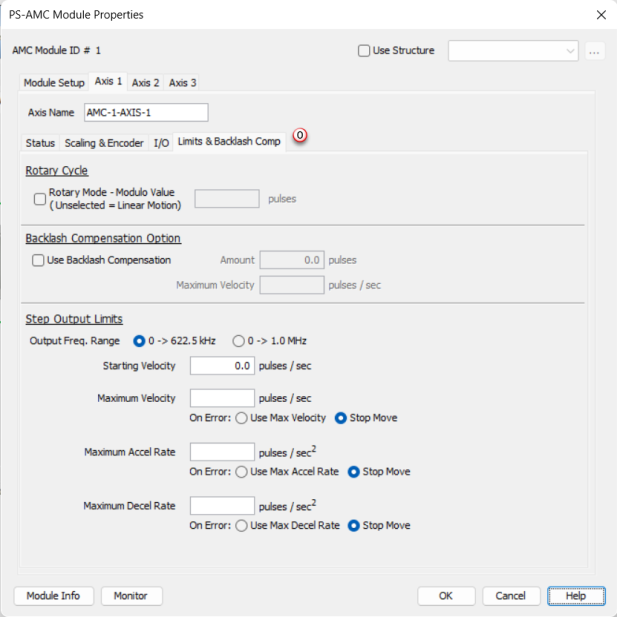
o. Limits & Backlash Comp Tab:
The channel output can be limited in the following ways:
Rotary Cycle
Rotary Mode - Modulo Value: If selected, when the count reaches the specified rollover position, the next positive pulse will reset the count to 0. Also, if the count is at 0, the next negative pulse will reset the count (roll under) to the specified (rollover position -1 ). The final scaled value must be within 1 and 2,147,483,647 pulse counts. When this feature is used, the count will always be a positive number between 0 and the (rollover position - 1). For example, if set for 10,000, valid positions will be in the range 0 – 9,999.
Backlash Compensation: When the direction changes, the module will output the number of pulses on the axis STP pins specified. The Current Position Feedback will not be updated with these pulses. The output will pulse at the rate specified in the Amount and Velocity fields.
Step Output Limits
Output Frequency Range: There are two selections for Output Frequency Range. The reason for the selection is for the divider logic that is used to produce the best stepping output for all frequencies in the range: the 0->622.5 kHz range is most common and works best for lower output frequencies. The 0->1MHz range works throughout the range however will produce slightly less symmetrical step waveforms at lower frequencies. As a general rule, use the default (0 to 622.5 kHz) unless you know you will need to go at a higher frequency than 622.5 kHz in your application.
Starting Velocity: The velocity to start at when accelerating to higher target velocities. This is typically set to the maximum rate the motor can instantaneously achieve from a stopped state. The system must be able to withstand the jerk created by this immediate velocity change. Using this feature can reduce acceleration / deceleration times, and therefore reduce process cycle times. For target velocities below the Starting Velocity, there is no acceleration / deceleration, and the profile will start and stop at the target rate without ramping.
Maximum Velocity: This is the maximum pulse rate that the module will output. The On Error selections specify how the module should behave when the maximum velocity is exceeded. The module can be configured to maintain the maximum rate or to Stop the move if a pulse rate higher than the maximum is specified by the logic.
Maximum Accel Rate: This is the maximum acceleration rate that the module will output. The On Error selections specify how the module should behave when the maximum velocity is exceeded. The module can be configured to maintain the maximum velocity or to Stop the move if an acceleration rate higher than the maximum is specified by the logic.
Maximum Decel Rate: This is the maximum Deceleration rate that the module will output. The On Error selections specify how the module should behave when the maximum accel rate is exceeded. The module can be configured to maintain the maximum accel rate or to Stop the move if a deceleration rate higher than the maximum is specified by the logic.
The minimum acceleration and deceleration rates for AMC moves is 120 steps / sec^2