|
|
Topic: P306 |
P2-02HSC |
|
|
|
Topic: P306 |
P2-02HSC |
|
The following section discusses the configuration and options available with the High-Speed Counter Module.
Note: A P2-02HSC cannot be installed in a remote base group when using the non-local I/O option.
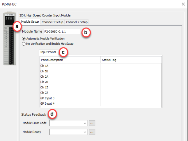
Input Points: There are 6 single-ended counter inputs and 2 general purpose inputs available which can be assigned a status tag (read only) so they can be monitored from within the ladder logic.
Note: The Input Points are not updated in STOP mode.
Module Error Code: Enter a tag in the field to reference any current Errors in the module from within the ladder logic. The table below describes the Errors possible.
Module Ready: This field accepts Boolean tags and is used to indicate that the module is installed, configured, and ready for instructions.
Note: If an error message is present due to a fault, once the fault is corrected, a power cycle or a triggering of an SPOS instruction will clear the error.
|
Error Bit |
Error |
Description |
|
1 |
Future |
Future |
|
2 |
Future |
Future |
|
3 |
Future |
Future |
|
4 |
Future |
Future |
|
5 |
Future |
Future |
|
6 |
Future |
Future |
|
7 |
Future |
Future |
|
8 |
Firmware Image CRC Error |
Module Firmware is faulted |
|
9 |
Future |
Future |
|
10 |
Future |
Future |
|
11 |
Future |
Future |
|
12 |
Future |
Future |
|
13 |
Future |
Future |
|
14 |
Future |
Future |
|
15 |
Future |
Future |
|
16 |
Future |
Future |
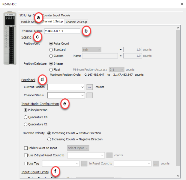
- Position Unit: Pulse: This option uses the raw Pulse per unit selection.
- Position Unit: Standard: This option configures the numbers of pulses per unit. There are five pre-defined labels that can be selected: inch, foot, mm, degree and revolution. The pulses can also be specified in fractional increments (.1).
- Position Unit: Custom: This option also configures the number of pulses per unit but allows for a custom label to be entered. The pulses can also be specified in fractional increments (.1).
- Position Datatype: The position may be specified in terms of Integer or Float. Integer will provide a greater range but may be difficult to use when using the Scaling function. Conversely, Float will provide greater resolution in some cases but will greatly limit the range. The more resolution specified, the lower the range. See the Understanding Maximum Position Cycle and Minimum Position Accuracy topic for more information.
- Current Position Feedback: Insert a tag into this field in order to reference the channel’s current High-Speed Count. The value will be represented in the scaled units specified from the Channel Scaling setup.
- Channel Status: Insert a tag into this field in order to reference the current Status of the channel. A list of the possible Channel Status codes are listed below:
|
Status Bit |
Status |
|
1 |
Alert - Current Position Out of Range of New Cycle. If in Rotary Mode, if the rollover to set to a position that is less than the current position. When this occurs, the old (currently running) rollover position will be active until the condition is corrected by either changing the rollover value to be greater than the current position, or by changing the current position to be less than the proposed new rollover position. |
|
2 |
Alert - Inhibit Active by Defined Input. The input that was defined to inhibit the count is active and therefore the current position is latched until the input is inactive. |
|
3 |
Future |
|
4 |
Future |
|
5 |
Future |
|
6 |
Inhibited - Reset Tag out of range1. This occurs when the tag or constant value used to store the position that will be set when the Set Positiontag becomes true has a value that is outside the Rollover Positionwhen Rotary Modeis enabled.
Note: The channel will be inhibited at all times that the value of the tag or constant is outside of the rollover range AND the Set Tag (Boolean) is TRUE. To clear this condition, change the position value to be within the rollover range or disable the Use Tag to Set Position feature. |
|
7 |
Inhibited - Z Reset out of range1. This occurs when the tag or constant value used to store the position that will be set when the Z input point is triggered has a value that is outside of the Rollover Position when Rotary Mode is enabled.
Note: The channel will be inhibited at all times that the value of the tag or constant is outside of the rollover range regardless if the input is triggered or not. To clear this condition, change the Position Value to be within the Rollover Range or disable the Z Reset feature. |
|
8 |
Inhibited - Rotary Rollover out of range1. This occurs when Rotary Mode is enabled AND the Rollover Position is <=0 OR is outside the Channel position range (i.e. larger than 8.3M when float scaling is selected). To clear this condition, change the Rollover Position value to greater than 0 AND be within the channel position range. |
|
9 |
Alert - Position Rolled Over |
|
10 |
Alert - Position Rolled Under |
|
11 |
Future |
|
12 |
Future |
|
13 |
Future |
|
14 |
Future |
|
15 |
Future |
|
16 |
Future |
- Pulse/Direction: This selection configures the module to receive the Pulse Train on Input A of the channel and to read the Direction on Input B of the channel. When the signal on Input B is low, the module will count up when receiving pulses on Input A. Conversely, when the signal on Input B is high, the module will count down when receiving pulses on Input A.
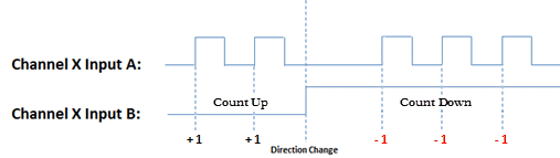
- Quadrature X1: With this selection, the channel count will depend on which input is leading and which is trailing. If the Direction Polarity is set to Increasing Counts = Positive Direction and Input A is leading Input B by a 1/2 pulse, then the count will increase by one with every rising edge of the pulse received on Input A.
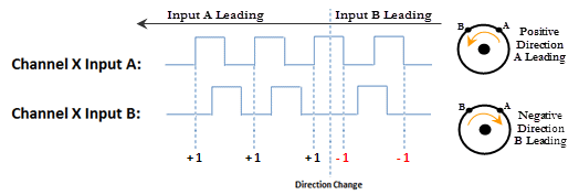
- Quadrature X4: As with the Quadrature X1 setting, the channel count is dependent upon which input is leading and which is trailing. With the Quadrature X4 selection however, the counts will increment on each rising and falling edge of both input pulse trains.
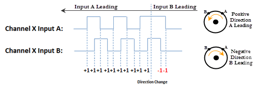
- Direction Polarity: This selection determines the direction polarity of the incoming signals.
- Increasing Counts = Positive Direction: With Pulse/Direction mode, if the signal on Input B is low, pulses on Input A will generate an increasing count. When the signal on Input B is high, pulses on Input A will generate a decreasing count.
With Quadrature mode, if the signal on Input A leads the signal on Input B, the count will increase. If the signal on Input B leads the signal on Input A the count will decrease.
- Increasing Counts = Negative Direction: With Pulse/Direction mode, if the signal on Input B is low, pulses on Input A will generate a decreasing count. When the signal on Input B is high, pulses on Input A will generate an increasing count.
With Quadrature mode, if the signal on Input A leads the signal on Input B, the count will decrease. If the signal on Input B leads the signal on Input A the count will increase.
- Inhibit Count on Input: Enabling this selection allows the user to specify an input that will be used to inhibit the count. The count will be inhibited when this specific input is in its active state. Valid inputs for this feature are: 1Z, 2Z, as well as, General Purpose (GP) Inputs 3 and 4.
- Use Z-Input Reset Count to: Enabling this feature will cause the count to reset to the specified count value when the Z Input for the channel goes to the active state. This value is specified in user units but the final scaled value must be within -2,147,483,647 and 2,147,483,647 whole counts. If the final scaled reset count value is not a multiple of whole pulses, the fractional pulse amount will be ignored.
- Use Tag... to Reset Count to: When the specified tag equals 1, the count for the channel will be reset to the specified count value. This value is specified in user units but the final scaled value must be within -2,147,483,647 and 2,147,483,647 whole counts. If the final scaled reset count value is not a multiple of whole pulses, the fractional pulse amount will be ignored.
- Rotary Encoder - Rollover Position: When the count reaches the specified rollover position, the next positive pulse will reset the count to 0. When the count is at 0, the next negative pulse will reset the count (roll under) to the specified rollover position. The value is specified in user units but the final scaled value must be within 1 and 2,147,483,647 whole counts. If the final scaled roll over position value is not a multiple of whole pulses, the fractional pulse amount will be ignored. When this feature is used, the count will always be a positive number between 0 and your rollover number.
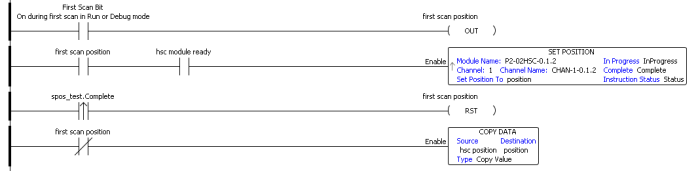
Note: On power cycle the current position is not retained. This will require additional ladder code. Example below: