|
|
Topic: P244 |
Registration (REG) Instruction |
|
|
|
Topic: P244 |
Registration (REG) Instruction |
|
Icon / Button = 
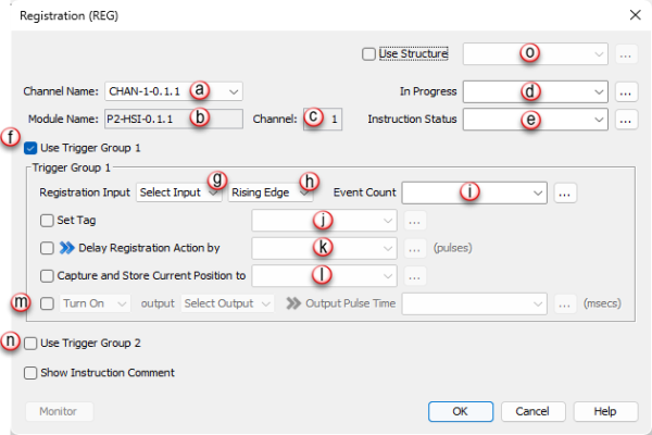
The Registration instruction can trigger several internal and external position based events. Inputs can be used to trigger the capturing of positions, setting a tag, counting events and turning on, off or pulsing an output.
|
Parameter |
Parameter Type |
Requirements |
Description |
|
Enable |
Ladder Input |
Must Have |
Level-driven. When Enable is ON, the instruction will operate every scan. When Enable is OFF, the instruction is not resolved and its Outputs are not updated. |
|
Channel Name |
Selectable Option with Drop-down Selection |
Must Have |
The selected channel this instruction will control. Each HSI module contains two independent channels. * See Note 1 below. |
|
Module Name |
Read Only |
Optional |
The Name of the module that contains the currently selected channel. Displayed for informational purposes only. |
|
Channel |
Read Only |
Optional |
The ID number of the currently selected channel. Displayed for informational purposes only. |
|
Instruction Status |
Numerical Tag |
Optional |
A Status tag that contains the Feedback of the triggered event. The HSI module runs asynchronously with respect to the ladder scan so this status should be used for interlocking logic if necessary. See the Instruction Status Table for bit definitions. |
|
In Progress |
Boolean Tag |
Optional |
A Status tag that specifies whether or not the instruction is active inside the CPU. This Status tag reflects the status of this individual REG instruction. |
|
Use Trigger Group 1 or 2 |
Checkbox |
Must Have |
Trigger Group 1 and Trigger Group 2 allow one Registration instruction to perform two separate actions. Select Trigger Group 1, Trigger Group 2 or both and configure the parameters accordingly. Trigger Group 1 and Trigger Group 2 both operate on the same channel. However, they are configured and operate completely independent of each other. Their functions can be paired together using the "Turn ON" and "Turn OFF" options. |
|
Registration Input ( Input Point Number ) |
Selectable Option with Drop-down Selection |
Must Have |
The input that will trigger the Registration action must be specified in this field. This input can be one of the two General Purpose Inputs or can be the Z Pulse Input for the channel. You must also specify whether the Registration is triggered by the Rising Edge or Falling Edge of this input. |
|
Event Count |
Numerical Tag |
Optional |
A numeric tag that contains a count of how many times the Registration instruction has been triggered. The count will reset to 0 whenever the instruction is disabled and re-enabled. |
|
Set Tag |
Boolean Tag |
Optional |
A Status tag that specifies whether or not the Registration event has been triggered. |
|
Delay Registration Action by |
Numerical Tag/Constant |
Optional |
The Registration action (Set Tag, Capture and Store, Turn On/Off/Pulse Output and Trigger Count) may be delayed by a set number of pulses specified in this field. * See Note 2 below. |
|
Capture and Store Current Position to |
Numerical Tag |
Optional |
A numeric tag that contains the channel input pulse count captured at the time of the Registration trigger. |
|
Turn On/Off Pulse On/Off Output |
Selectable Option with Drop-down Selection |
Optional |
Specifies the action taken by the Registration instruction once triggered. The HSI output may be set ON, set OFF, pulsed ON or pulsed OFF. The amount of time the pulse is ON or OFF may be specified by a numeric tag or constant. |
|
User Structures |
Check Box |
Optional |
Enables the use of Structures |
* Note 1: Only one REG Instruction at anytime can be enabled per channel.
* Note 2: If the channel is stopped or moving in the positive direction, the Delay By feature will occur after the specified counts are reached in the positive direction. If the channel is moving in the negative direction, the Delay By feature will occur after the specified counts are reached in the negative direction. However, if a direction change occurs previous to achieving the delay by "Execution" position, the delay by "Trigger Point" is not recalculated and will not occur in the opposite direction.
|
Item |
Requirement |
Exceptions |
|
Event Count |
N/A |
Will be reset to zero at the start of the instruction (at 65535 the count will rollover to 0). |
|
Delay Registration Action by (Delay Value) |
Must be within the range of 1 and 8.4e6. |
If the delay amount is outside of the valid range, then the action will be Aborted. The Aborted - Trigger 1 - Delay out of range or Aborted - Trigger 2 - Delay out of range bit will be set in the Command Status tag. |
|
Output Control (Output Pulse Time) |
Must be within the range of 1ms and 65535ms. |
If the output pulse time is outside of the valid range, then the action will be Aborted. The Aborted - Trigger 1 - Pulse Time out of range or Aborted - Trigger 2 - Pulse Time out of range bit will be set in the Command Status tag. |
Note: All parameters are checked before the instruction becomes active. If a parameter violates one of the rules, the instruction will be aborted before any action occurs.
When the Registration instruction is selected the window shown below opens with defaults shown.
Note: If the value of the tag changes prior to the trigger of the Registration Input, the new value will be applied. If after, the new value will be applied on the next trigger of the Registration Input or an on/off transition of the Enable.
In the following example, the Registration Instruction is being used to control a pneumatic stamping system. As blank refrigerator magnets are fed onto the belt, the sensor on the in-feed end determines if the magnet is centered on the belt and, if so, triggers the Registration event. The belt mounted encoder tracks each magnet as it travels through the stamping system. The Delay Registration Action by option of the instruction allows the stamping to be delayed until the magnet is directly under the pneumatic stamp. The operation is as follows:
A blank magnet is detected and the instruction is triggered. The output or stamping function is delayed by the appropriate number of encoder pulses. Once the magnet travels to the precise location under the stamp, the pneumatic stamp is activated and the image is stamped onto the magnet.
|
Status Bit |
Description |
|
1 |
Future |
|
2 |
Future |
|
3 |
Future |
|
4 |
Future |
|
5 |
Aborted - IO Fault (See Module Error Register) |
|
6 |
Future |
|
7 |
Aborted - Position out of range |
|
8 |
Aborted - Trigger 1 - Invalid input selected |
|
9 |
Aborted - Trigger 1 - Delay out of range |
|
10 |
Aborted - Trigger 1 - Pulse Time out of range |
|
11 |
Future |
|
12 |
Aborted - Trigger 2 - Delay out of range |
|
13 |
Aborted - Trigger 2 - Pulse Time out of range |
|
14 |
Aborted - Communication failure during instruction |
|
15 |
Future |
|
16 |
Future |


 indicates that this value can be changed while the instruction is running. See Note below.