Topic: P231

Find Home (HOME) Instruction

Mnemonic (Keyboard Shortcut) = HOME

Icon / Button =

Purpose

The Find Home instruction allows the user to run a variety of homing routines. Homing is needed to bind the HSO channel or AMC axis position to that of a real world physical position. Generally homing is only necessary on power up of a machine that incorporates incremental positional feedback. Of course, homing may be needed at other times as well depending on the application.

Note: The Position Limits are disabled during a Homing Move. The Hardware Limit Switches still apply.


Instruction Parameters

Parameter

Parameter Type

Requirements

Description

Enable

Ladder Input

Must Have

Level-driven.  When Enable is ON, the instruction will operate every scan.  When Enable is OFF, the instruction is not solved and its outputs are not updated.

Axis/Channel Name

Selectable Option with Drop-down Selection

Must Have

The selected channel/axis this instruction will control. Each HSO module contains two independent channels. Each AMC module provides from 1 to 4 axes depending on the model number.

Module Name

Read Only

Optional

The Name of the module that contains the currently selected channel. Displayed for informational purposes only.

Axis/Channel

Read Only

Optional

The ID number of the currently selected channel/axis. Displayed for informational purposes only.

In Progress

Boolean Tag

Optional

A Status tag that specifies whether or not the instruction is active inside the CPU. This Status tag reflects the status of this individual HOME move. The HSO or AMC module runs asynchronously with respect to the ladder scan so this status should be used for interlocking logic if necessary. This tag is immediately set to 1 when the instruction is enabled unless the module is currently executing another instruction on the same channel/axis. When the CPU receives Feedback that the command has completed, this tag is set to 0.

Complete

>Boolean Tag

Optional

A Status tag that specifies whether or not the instruction has been completed inside the CPU. This Status tag reflects the status of this individual HOME move. The HSO or AMC module runs asynchronously with respect to the ladder scan so this status should be used for interlocking logic if necessary. When the CPU receives Feedback that the command has completed, this tag is set to 1.

Move Status

Numerical Tag

Optional

A Status tag that contains the Feedback of the Action being performed by this instruction. The HSO or AMC module runs asynchronously with respect to the ladder scan so this status should be used for interlocking logic if necessary. See the Move Status Table for bit definitions.

Mode Selection

Selectable Option

Must Have

Select one of four homing mode routines to be performed. See the Mode Examples below.

Initial Travel Direction

Selectable Option

Must Have

Specifies the initial direction to travel while seeking the home position.

Switch 1

Selectable Option with Drop-down Selection

Must Have

Specifies the Input to use for Switch 1. Must be a general purpose input on the HSO or AMC module.

Switch 2

Selectable Option with Drop-down Selection

Must Have (dependent on Homing Mode selected)

Specifies the Input to use for Switch 2. Must be a general purpose input on the HSO or AMC module.

Edge 1

Selectable Option

Must Have

Specifies the edge (rising or falling) to act on for Switch 1.

Edge 2

Selectable Option

Must Have (dependent on Homing Mode selected)

Specifies the edge (rising or falling) to act on for Switch 2.

First Speed

Numerical Tag/Constant

Must Have

A value (represented in the units indicated) that specifies the initial speed to travel while seeking Switch 1.

Second Speed

Numerical Tag/Constant

Must Have
(if Mode 1 or 4 selected)

A value (represented in the units indicated) that specifies the final approach speed used in Modes 1 and 4. This is typically a slower speed in order to achieve better precision.

Accel Rate

Numerical Tag/Constant

Must Have

A value (represented in the units indicated) that specifies the acceleration rate used for both the First Speed and Second Speed ramps.

Decel Rate

Numerical Tag/Constant

Must Have

A value (represented in the units indicated) that specifies the deceleration rate used for both the First Speed and Second Speed ramps.

Set Position To

Numerical Tag/Constant

Optional

A value (represented in the units indicated) that defines what the new position will be when the home move is completed.


Note: The Feedback received for the Status tags can take one or more scans to register within the CPU depending on the CPU scan time and processing delays within the HSO or AMC module

Instruction Rules


Item

Requirement

Exceptions

Position Limits

Position Limits are ignored during all homing moves. Homing of a machine generally implies that the position, prior to finding home, is inaccurate, so the Position limits also have to be considered inaccurate.

• If your channel/axis has only one physical limit, you must ensure that the Travel Direction is set to the direction of your physical limit or the channel/axis will over-travel indefinitely in the opposite direction.


Position Limits are not re-enabled until after the entire homing routine has completed. If you use Mode 3 and the configured decel rate would cause motion beyond a Position limit in part 3 of the move, the machine will travel past the Position limit without error. Future move commands will be restricted to travel in the opposite direction until you are back on the safe side of the Position Limit.

Acceleration and Deceleration Ramp Rate

The Ramp Rate must be within the range of 1 to 100e6 and not exceed the user's Maximum Accel or Decel Rates (configured in the HSO module's Channel Configuration or AMC module's Axis Configuration)

• If the Ramp Rate exceeds the module's valid range, then the move will be Aborted. The Aborted - Accel/Decel/Ramp out of range bit will be set in the Move Status tag.


• If the Ramp Rate exceeds the Maximum Accel or Decel Rates and the Stop Moveoption was selected (both configured in the HSO module's Channel Configuration or AMC module's Axis Configuration), then the move will be Aborted. The Aborted - Over User’s Max Accel or Aborted - Over User's Max Decel bit will be set in the Move Status tag.


• If the Ramp Rate exceeds the Maximum Accel or Decel Rates and the Use Max Accel Rate or Use Max Decel Rate option was selected (both configured in the HSO module's Channel Configuration or AMC module's Axis Configuration), then the configured Max Accel or Max Decel rate will be used and the target Velocity will NOT be achieved as quickly as desired, if at all. The Alert - Parameter Adjusted: Over User's Max Accel or Alert - Parameter Adjusted: Over User's Max Decel bit will be set in the Move Status tag and the resulting profile will take longer to travel to the specified target.


• If a home switch is reached while accelerating or decelerating, the Alert - Target Reached During Accel/Decel alert bit will be set in the Move Status tag. Homing accuracy is affected by the travel speed at the time the home switch is tripped. To ensure repeatable accuracy, you must adjust your parameters or move further away from home and re-home so that the switch is reached at a steady speed.

Set Position

Specified in terms of user position units. The resulting scaled target must be within the absolute range of -2,147,483,647 to 2,147,483,647 pulses on a /1 decimal scale.

If a /10, /100, etc. decimal scale is selected, the range will be reduced by that factor. i.e. a /10 scale reduces the range to

-214,748,364.7 to 214,748,364.7

• If the specified position exceeds the absolute range of the HSO or the module's Rotary Encoder - Rollover Position range (configured in the HSO module's Channel Configuration or AMC module's Axis Configuration), then the instruction will be Aborted. The Aborted - Target out of range bit will be set in the Move Status tag and the position will not change.


• If the specified position exceeds the Position Limit (configured in the HSO module's Channel Configuration or AMC module's Axis Configuration), then the instruction will be Aborted. The Aborted - Target out of range bit will be set in the Move Status tag

Velocity (First Speed and Second Speed)

Specified in terms of user velocity units. The resulting scaled pulse rate must be within the range of 1Hz to 1MHz.

• If a value greater than 1MHz is specified and no Maximum Pulse Rate is configured in the HSO module's Channel Configuration orAMC module's Axis Configuration, then the move will be Aborted. The Aborted - Velocity out of range bit will be set in the Move Status tag.


• If a value less than 1Hz is specified, then the move will be Aborted. The Aborted - Velocity out of range bit will be set in the Move Status tag.


• If the velocity exceeds the user configured Maximum Pulse Rate and the Stop Move option was selected (both configured in the HSO module's Channel Configuration or AMC module's Axis Configuration), then the move will be Aborted.The Aborted - Over User’s Max Velocity bit will be set in the Move Status tag.


• If the velocity exceeds the user configured Maximum Pulse Rate and the Use Max Pulse Rate option was selected (both configured in the HSO module's Channel Configuration or AMC module's Axis Configuration), then the Maximum Pulse Rate will be used and the Alert - Parameter Adjusted: Over User's Max Velocity will be set in the Move Status tag.

Edge Transitions

There must be a minimum of 1ms between edge transitions if using a single switch in Mode 1.

If the velocity and distance between switches results in edge transitions that are faster than 1ms, the transition may not be recognized and the machine may overtravel indefinitely.


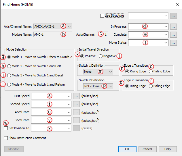
Note: All parameters are checked before the motion begins. If a move violates one of the rules, the instruction will be aborted before any motion occurs.


Note: The instruction may not function correctly if the axis is being used in another instruction in ladder. If two separate instructions in ladder use the same axis, the latest one (in the scan cycle(s)) controls the axis.

Instruction Configuration

When the Find Home Instruction is selected, the window shown below opens with defaults shown.


Parameter Configuration Table

Find Home

Instruction

(HOME)

Notes

Axis/Channel Name


Select from the list of available configured HSO channels and AMC axes.

Module Name


Read-Only: Module name that contains the selected channel/axis.

Axis/Channel


Read Only: channel/axis number of the selected channel/axis.

In Progress


Enter the tag that will contain the move's In Progress status.

Complete


Enter the tag that will contain the move's Complete status.

Move Status


Enter the tag that will contain the Status of the move in progress.

Mode Selection 1


Select if the Move to Switch 1 then to Switch 2 profile is desired.

Mode Selection 2


Select if the Move to Switch 1 then Halt profile is desired.

Mode Selection 3


Select if the Move to Switch 1 then Decel profile is desired.

Mode Selection 4


Select if the Move to Switch 1 and Return profile is desired.

Initial Travel Direction - Positive


Select the Positive direction for the start of the homing move. This means the move counts will be increasing in this direction.

Initial Travel Direction - Negative


Select Negative direction for the start of the homing move. This means the move counts will be decreasing in this direction.

Switch 1 Definition


The Input used to trigger completion of the first homing event. In some cases, this may be the only homing event. The list of possible inputs is taken from the module configuration for the selected channel/axis. Must be a general purpose input on the module.

Edge 1 Definition - Rising


Select the Rising Edge of Switch 1 to indicate the first move is complete.

Edge 1 Definition - Falling


Select the Falling Edge of Switch 1 to indicate the first move is complete.

Switch 2 Definition


The Input used to trigger completion of the second homing event. The list of possible inputs is taken from the module configuration for the selected channel/axis. Only used when Mode 1 is selected. Must be a general purpose input on the module.

Edge 2 Definition - Rising


Select the Rising Edge to indicate the second move is complete. Only used when Mode 1 or Mode 4 is selected.

Edge 2 Definition - Falling


Select the Falling Edge to indicate the second move is complete. Only used when Mode 1 or Mode 4 is selected.

First Speed


Sets the First Speed ( defined in the units indicated ) of the homing routine. The value used will not exceed the maximum velocity defined in the channel/axis configuration.

Second Speed


Sets the Second Speed ( defined in the units indicated ) of the homing routine. The value used will not exceed the maximum velocity defined in the channel/axis configuration.

Accel Rate


Sets the Acceleration that the homing move will use. The value used will not exceed the maximum acceleration defined in the channel/axis configuration.

Decel Rate


Sets the Deceleration that the homing move will use. The value used will not exceed the maximum deceleration defined in the channel/axis configuration.

Enable "Set Position To"


Select the check box to enable the Set Position To option.

Set Position To


This value will be set as the current position once the homing routine is completed. If not defined, zero will be used.

Application Example

The following example demonstrates how the Find Home (HOME) instruction can be utilized in a Tea Pot Pick and Place system. On power up, shutdown or any other time it may be required the Homing instruction can be executed in order to initialize or reset the system. For this example, the HOME instruction will be set to Mode 1. When the instruction is enabled, the gantry arm will accelerate to the First Speed Selection and travel at that speed until Switch #1 is triggered. The gantry arm will then decelerate to the Second Speed Selection and travel at that speed until Switch #2 is triggered. Once Switch #2 is triggered, the gantry arm will stop.

Timing Charts

Note: The Complete Status and Move Status updates may also be delayed by the Accel Rate, Decel Rate and Stop Setup options selected.

Mode Examples

Mode 1

Move to Switch 1 then to Switch 2.

1. Accelerate to First Speed.

2. Travel at First Speed until Edge 1 of Switch 1 occurs.

3. Decelerate to Second Speed.

4. Travel at Second Speed until Edge 2 of Switch 2 occurs.

5. Immediately Stop and optionally set the position to a user specified value.

Note: In Mode 1, depending on direction of travel, if Switch 2 is made prior to Switch 1 the move will halt.


Mode 2

Move to Switch 1 and Halt.

1. Accelerate to First Speed.

2. Travel at First Speed until Edge 1 of Switch 1 occurs.

3. Immediately Stop and optionally set the position to a user specified value.


Mode 3

Move to Switch 1 and Decelerate.

1. Accelerate to First Speed.

2. Travel at First Speed until Edge 1 of Switch 1 occurs.

3. Optionally set the position to a user specified value at Switch 1.

and Decelerate to a Stop.

Mode 4

Move to Switch 1 and Return.

1. Accelerate to First Speed.

2. Travel at First Speed until Edge 1 of Switch 1 occurs.

3. Decelerate to a Stop.

4. Accelerate to Second Speed in the opposite direction.

4b. Travel at Second Speed until Edge 2 of Switch 1 occurs.

5. Immediately Stop and optionally set the position to a user specified value.

Flow Charts


Rung Example


Move and Instruction Status Table


Status Bit

Status

Description

1

Px-HSO: Accelerating

This bit shows the current state of the channel while movement is accelerating (when In Progress Bit = ON). After the instruction is Complete, this bit will be OFF. 

PS-AMCx: General Use Status 1

AREG: Waiting For Master Event

FCO: Waiting for Event Start

GEAR: Primary Drivetrain Slave is Enabled

MREG: Correction Move In Progress

MSEQ: Dwell Period of Timeout is Active

RTA: Table stopped at station

2

Steady Velocity

This bit shows the current state of the channel or axis while movement is running in steady state (when In Progress Bit = ON). After the instruction is Complete, this bit will be OFF. 

3

Px-HSO: Decelerating

This bit shows the current state of the channel while movement is decelerating (when In Progress Bit = ON). After the instruction is Complete, this bit will be OFF. 

PS-AMCx: General Use Status 2

AREG: Waiting For Product Event

FCO: Tool Slewing to Synchronization

GEAR: Secondary Drivetrain Slave is Enabled

RTA: Alert: Invalid Absolute Station Id

4

Px-HSO: Future

Future

PS-AMCx: General Use Status 3

AREG: Correction Applied

FCO: Tool is in Synchronization with the Master

GEAR: Third Drivetrain Slave is Enabled

MREG, SMOV, VMOV: Position Capture Occurred (1 or 2 scan pulse)

5

Px-HSO: Future

Future

PS-AMCx: General Use Status 4

GEAR: Fourth Drivetrain Slave is Enabled

6

Px-HSO: Future

Future

PS-AMCx: Application Move

Info – Application Move is in Progress (Movement or active slave )

7

Stopped at Move Target

This bit is ON when the instruction completes and the Target position was achieved without any Errors or Aborts.

8

Stopped at Registration Target

This bit is ON when the instruction completes a Registration function using the Decel to a Stop option without any Errors or Aborts.

9

Aborted - Instruction Disabled

This bit indicates that the instruction was disabled in the ladder by the user

10

Aborted - Hit Limit (See Channel or Axis Status Register)

This bit indicates that either a Limit Switch or Position Limit has been tripped. The Channel or Axis Status will indicate which of the 4 possible conditions has occurred.

11

Aborted - Communications Failure During Move

This bit indicates that communication to the module failed previously. The module may now be ready but the current instruction must be restarted. This condition may occur due to a hot-swap or a loss of communication to a Remote Slave Base.

12

Aborted - IO Fault (See Module Error Register)

If the ESCP (Electronic Short Circuit Protection) becomes active for the Output Channels associated with the current instruction, the instruction will abort since the intended operation will fail. This bit will turn ON and the specific Channel error can be found in the Module Error Code, Bits 2 & 3.  Note: Faults on Channels 3-6 will not cause this abort and must be detected using the Channel Status and Module Error Code.

13

Aborted - Over User's Max Accel

In the HSO H/W Configuration Channel setup or the PS-AMC Axis Configuration, the user has the option to either Limit a move to a maximum value or Stop the move once that maximum value is exceeded. If the Channel or Axis is configured to Stop the Move and the instruction exceeds the Maximum value, the instruction will Abort and one of these related bits will turn ON.

14

Aborted - Over User's Max Decel

15

Aborted - Over User's Max Velocity

16

Px-HSO: Aborted - Position Limit out of range

If the tag values assigned to the Position Limits are out of range, the instruction will Abort and this bit will be ON. Note: Affected by Channel Scaling.

PS-AMCx: Future

Future

17

Px-HSO: Aborted - Target out of range

When Position Limits are configured and the Instruction Target position is known to be beyond the Position Limits, the Instruction will Abort before any motion starts and this bit will be set ON. Note: Affected by Channel Scaling.

PS-AMCx: Abort Invalid Input/Edge Combination

This will occur when an axis is configured for RPI ( Reset Position by Input ) and that axis is running an instruction ( or it’s slave ) and tries to use the same input as RPI with a different edge.

18

Aborted - Velocity out of range

The HSO outputs can be run at a maximum of 1MHz. If the instruction commands a velocity greater than 1MHz, the instruction will Abort with this bit ON. Note: Affected by Channel Scaling.

19

Aborted - Accel/Decel/Ramp out of range

If the value assigned to the Acceleration or Deceleration Ramp is outside the valid range (1 to 100e6), the instruction will Abort and this bit will be ON. >Note: Affected by Channel Scaling.

20

Aborted - Jerk/S-Curve out of range

If the Jerk value is outside the valid range of 1 to 100e9or the S-Curve value is outside the range of 1 to 100e6, the instruction will Abort and this bit will be ON. Note: Affected by Channel Scaling.

21

Px-HSO: Future

Future

PS-AMCx: Axis Status

Additional information will be stored in the Axis Status register tag

22

Px-HSO: Future

Future

PS-AMCx: Aborted - General Parameter

There is a general parameter out of range ( does not include velocity, ramps, jerk, registration, or presets )

23

Px-HSO: Future

Future

PS-AMCx: Aborted – Preset Parameter

There is a preset parameter out of range

24

Aborted - Registration parameter out of range

At least one of the Registration input parameters is out of range. Parameters such as: Delay Registration Action by, Decel to a Stop or Output Pulse Time.

25

Alert - Target reached during Accel/Decel

If a home switch is reached while accelerating or decelerating, this bit will be set. To ensure repeatable accuracy, you must adjust your parameters or move further away from home and re-home so that the switch is reached at a steady speed.

26

Alert - Parameter Adjusted: Over User's Max Accel

In the HSO H/W Configuration Channel setup, the user has the option to either Limit a move to a maximum value or Stop the move once that maximum value is exceeded. If the Channel is set to Use the Maximum Value and the instruction exceeds this value, the instruction will not Abort and the output will be limited to the Maximum Value with the related Alert bit set to ON.

27

Alert - Parameter Adjusted: Over User's Max Decel

28

Alert - Parameter Adjusted: Over User's Max Velocity

29

Px-HSO: Alert - Position Rolled Over

These bits are set to report the occurrence of a Roll Over and/or Roll Under. They will remain set for 3 scans and then clear. This makes it possible to detect multiple roll over and/or roll under events using ladder code. The default rollover positions are +/- 2,147,483,647 but Channel Scaling affects this range and if Rotary Mode is enabled, the range will always roll under at zero, and roll over to zero.

30

Px-HSO: Alert - Position Rolled Under

31

Future

Future

32

Future

Future


Related Videos: