|
|
Topic: P050 |
Hardware Configuration |
|
|
|
Topic: P050 |
Hardware Configuration |
|
The Hardware Configuration tool is used to assign and configure Productivity Hardware, GS/DURApulse series drives, Protos X Field I/O, PS-AMC motion controllers, and various communication features within a project.
The following Parameters can be configured:
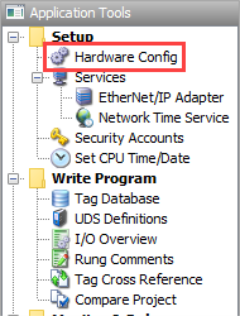
The Hardware Configuration tool can be accessed by selecting Hardware Config from the Setup Menu located on the Main Menu, under the Setup topic located on the Application Tools window, or by selecting the Hardware Config icon located on the setup toolbar, all shown below.
Once selected, the Hardware Configuration Window shown below will open.
New Configuration: This
option removes all the current hardware, deletes all unused tags,
and converts all used tags with "Was_" prefix for each tag name. See the
Project Conversion
topic for more information.
Convert To: Allows the
option for Converting a
project between product series. See the
Project Conversion
topic for more information.
Allow program to run with this system disconnected ( Hot
Swap):
This option will
Enable the "
Hot Swap" option for every unit in that base group (P2000 and P3000 only).
See the
Hot Swap Information
topic for more information.
Stop program when this system is disconnected: Applies the "Automatic Module Verification" option for every unit in that base group. See the Hot Swap Information topic for more information.
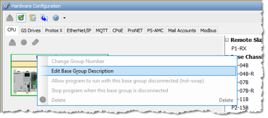
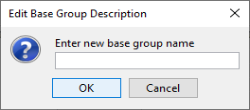
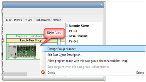
Right-click to edit description: Allows a custom name to be assigned to a Base Group. Right click on the Base Group and select Edit Base Group Description. Up to 32 characters are allowed for a Base Group Name.
Note: Default I/O tags deselected is useful when I/O tags were already created using Tag I/O Assignment.
The Productivity Suite Programming Software has the ability to Automatically detect any connected Hardware that is currently Online. The following steps show the quickest way to get started with Automatic Configuration:
- The Hardware Configuration window will query the system to discover installed Hardware.
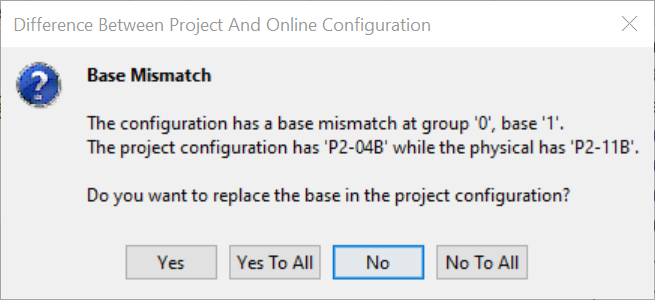
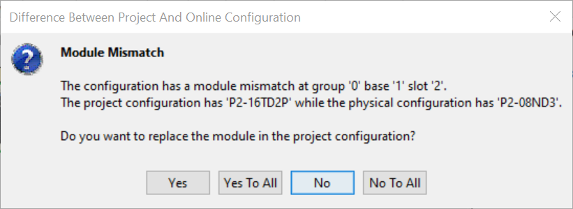
- A Base Mismatch or Module Mismatch message, shown below, may display because the default configuration will not match yours. To confirm the Base type select Yes. To confirm each Module select Yes to each or confirm all Modules at once by selecting Yes To All.
Note: Be sure all Remote I/O, AMC modules, and GS Drives have unique addresses, also called node numbers. Rotary switches set the P1, P2 and P3 remote module and PS-AMC addresses, GS4 and GS20 addresses are set from the drive communications setup menu. DIP switches set ProtosX and GS-EDRV100 addresses.
|
Hardware and Communication Limits |
P3000 |
P2000 |
P1000 |
|||
|
Reduced Limits |
System Limits |
Reduced Limits |
System Limits |
Reduced Limits |
System Limits |
|
| PS-AMC groups | 4 | 4 | 4 | 4 | 1 | 1 |
| P3-EX supported with CPU/RS/RX | 2 | 4 | Not Supported | Not Supported | Not Supported | Not Supported |
| RS or RX groups set to 'LOCAL' | 0 | 4 | 0 | 4 | 0 | 4 |
| P1 Ethernet Remote Base | Not Supported | Not Supported | 8 | 8 | 4 | 4 |
| P2 Ethernet Remote bases | Not Supported | Not Supported | 8 | 8 | Not Supported | Not Supported |
| P3 Ethernet Remote bases | 12 | 16 | Not Supported | Not Supported | Not Supported | Not Supported |
| Protos X, max number of bus-couplers | 4 | 4 | 4 | 4 | 4 | 4 |
| Protos X, max number of I/O modules | 32 | 32 | 32 | 32 | 32 | 32 |
| Protos X, max number of I/O modules per system | 32 | 32 | 32 | 32 | 32 | 32 |
| Intelligent Modules in Base Note that HSC and PWM modules follow the ordinary IO limits | 11 | 11 | 11 | 15 | Not Supported | Not Supported |
| Intelligent Modules in Group Note that HSC and PWM modules follow the ordinary IO limits | 11 | 11 | Not Supported | Not Supported | Not Supported | Not Supported |
| Intelligent Modules in System* (See Note 2) | 22 | 22 | 22 | 22 | Not Supported | Not Supported |
| GS Drives: GS-EDRV100 (GS1,2,3) and/or Modbus TCP (GS4, GS20, GS30) modules on Remote I/O port | 16 | 32 | 8 | 16 | 8 | 16 |
| Modbus TCP client connections (CPU Master) | 32 | 32 | 8 | 32 | 8 | 16 |
| Modbus TCP server connections (CPU Slave) | 16 | 32 | 8 | 16 | 8 | 16 |
| EtherNet/IP Adapter/Server connections *(See Note 1) | 4 | 4 | 4 | 4 | 4 | 4 |
| EtherNet/IP Scanner/Client Devices *(See Note 1) | 32 | 32 | 32 | 32 | 32 | 32 |
| CIP Connections per Device *(See Note 1) | 4 | 8 | 4 | 8 | 4 | 8 |
| Total CIP connections *(See Note 1) | 64 | 128 | 64 | 128 | 64 | 128 |
|
Note: System Limits represents the maximum allowed limits for a system, however if more than one of these limits is achieved, possible CPU and Communication performance issues may result. Please refer to the Reduced Limits if this occurs. |
||||||
|
Note 1: EtherNet/IP is not supported on the P3-530 |
||||||
|
Note 2: Only 11 (P3) or 15 (P2) total SCM's are allowed in a system, only 4 total AMC's (P3 or P2); other Intelligent Modules (HSI and/or HSO modules) can be added to meet the 22 limit. P2000 can support a combination of any intelligent module, P2-HSO, P2-HSI, P2-SCM, and PS-AMC modules, subject to the SCM and AMC maximums. P1000 supports one PS-AMC module |
||||||
|
Note 3: A P2000 CPU supports a maximum combination of 8 P2000 Ethernet Remote Bases and PS-AMC modules. |
||||||
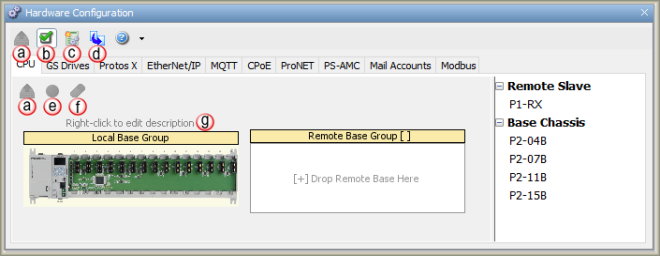
Hardware may also be added Manually while the CPU is Offline. With the CPU Offline, open the Hardware Configuration window. Looking at a cutout of this window shown below, note that the window is divided into three sections, which are also described below.
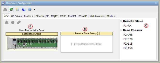
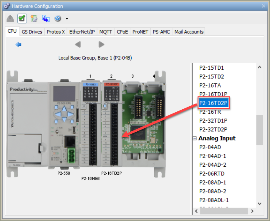
To change the Base Chassis size, click on the desired chassis size from the Component List and drag and drop to the desired Base Group.
A single Productivity Suite System build will allow the addition of up to 16 Remote Base Groups (RBG). This section will show how to manually add an RBG to your Hardware Configuration.
Left-click the desired
Base Chassis size from
the Components List and
drag it over to the
[+] Drop Remote Base Here
place holder. 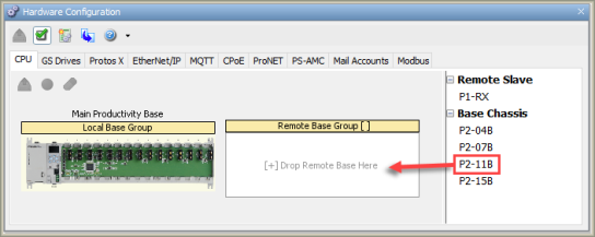
Note: Ensure the Remote Base Group Number matches the rotary switches that are set on the remote slave module (P3000/P1000) or base (P2000).
To Edit the Remote Base Group Configuration or the Local Base Group Configuration, double click on the respective Base Group in the Base Group(s) view.
For Productivity3000 systems, when Editing Remote Base Groups, click and drag any Base into the System and the P3-RS is automatically assigned to the first slot in the Base. You can change the P3-RS default selection by double-clicking the Base Group and then selecting the P3-RX in the Hardware Components section.
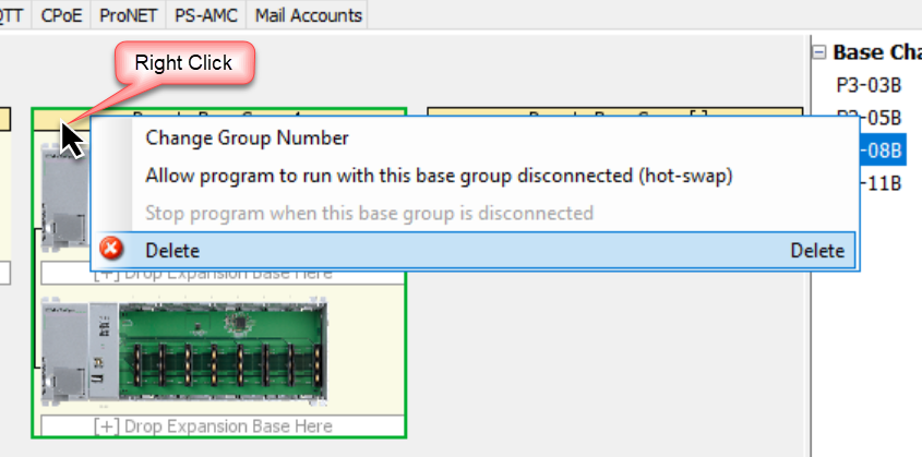
For Productivity3000 systems, you have the ability to move bases in the same group, move bases to another group and change the order of bases by dragging the desired base and dropping it in one of the areas labeled [+] Drop Expansion Base Here. The Remote Base Group number can be changed by right-clicking the area inside the Remote Base Group but outside of any bases. From the right-click menu select the Change Group Number option.
Two bases can be swapped by dropping an existing base on top of another one.
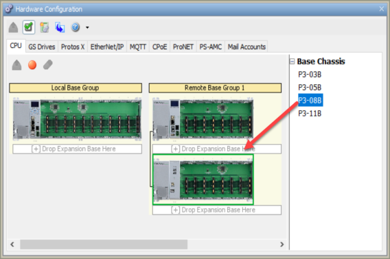
Up to four P3-EX Expansion Bases can be Added to any Local or Remote Base Group (Productivity3000 only). The Expansion Bases are Added to the Local CPU Base Group and the Remote Base Groups in the same manner.
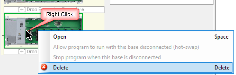
The Delete option allows removal of an individual local or remote expansion base or an entire remote group.
To delete an individual local or remote expansion base:
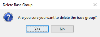
To delete an entire remote group:
Modules for the Productivity Suite CPU include the CPU, Discrete Input Modules, Discrete Output Modules, Analog Input Modules, Analog Output Modules, Analog Combination Modules and Specialty Modules. The number of Modules that can be added to each Base depends on the number of slots included on the Base. To Add Modules, do the following:
Note: See module limits in Hardware and Communications Limits table above.
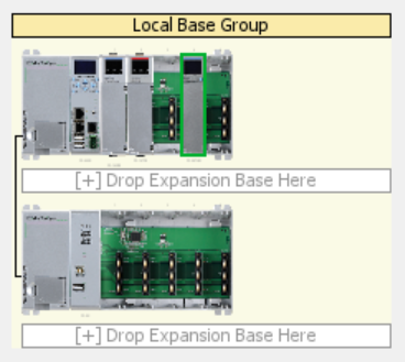
Once a module is added to a base, that module can be deleted or moved to another slot in the same base or to another base.
Moving a module from one slot to another slot, or even from one base to another, can be completed from the Group Overview window:
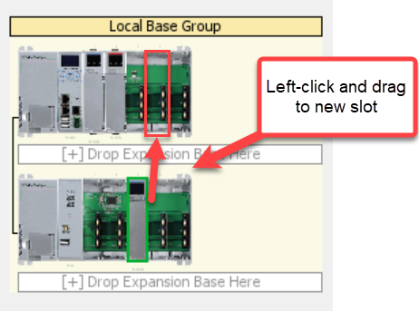
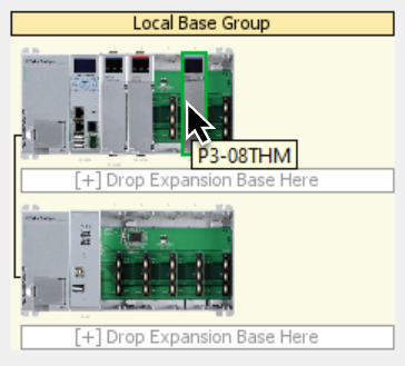
Note: You can use
your mouse to hover over the module to view the part number of the
module you would like to move.
To swap two modules, select one of the modules by left-clicking it then drag it to the slot containing the other module. The following dialog will appear, providing the option to either swap or delete the module that you are trying to replace.
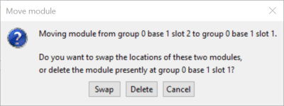
Note: Remember when moving or swapping a module, the tags associated with that module will be automatically adjusted when assigned in ladder.
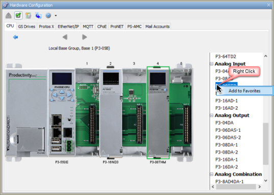
Commonly used modules can be saved to a Favorites list for future use.
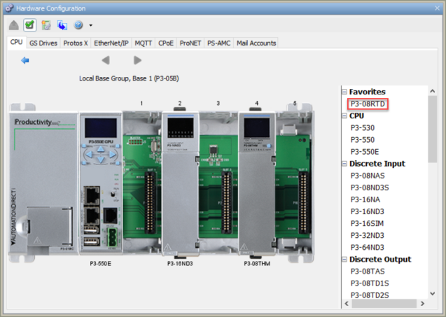
To remove a module from the Favorites list, right-click on the module in Favorites and select Remove from Favorites.
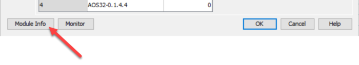
The Productivity Suite Hardware Components have Revision and Manufacturing Information stored internally. The P Series CPU, Remote Slaves (RS or RX) , Local Expansion (EX) and I/O ModuleInformation can be accessed by selecting the Module Information button located in the Configuration window of the Component as shown below.
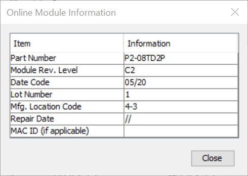
This is an example of the window displayed when Module Info is selected.
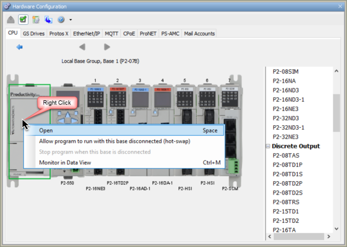
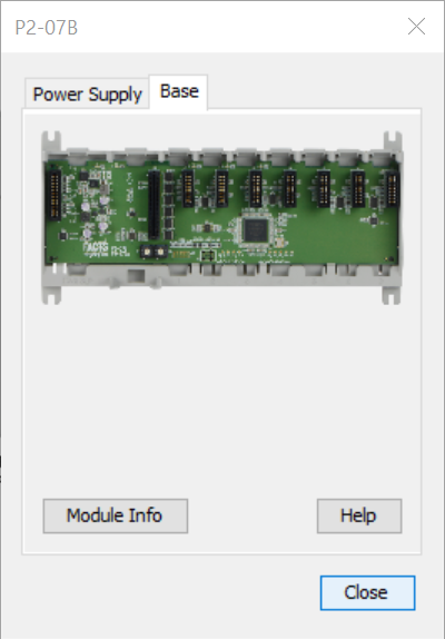
The Power Supply and Base Information is accessed by right-clicking on the Power Supply and selecting Open as shown below or by double-clicking on the Power Supply image.