Description
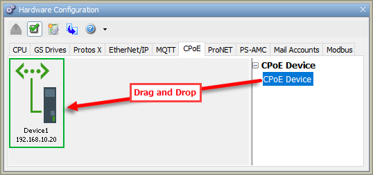
To configure your Custom Protocol over Ethernet Device, use the
setup tools found in the Hardware Configuration window. The
Custom Protocol over Ethernet options are found under the
CPoE tab of the Hardware Configuration window as shown
below. To configure a CPoE device, click and drag a device from the
right-hand column onto the CPoE palette.
Note: A maximum of 32
CPoE devices can be
configured.
Once a device has been placed on the palette, the following
Custom Protocol over Ethernet Device Properties
window appears:
Custom Protocol over Ethernet Configuration
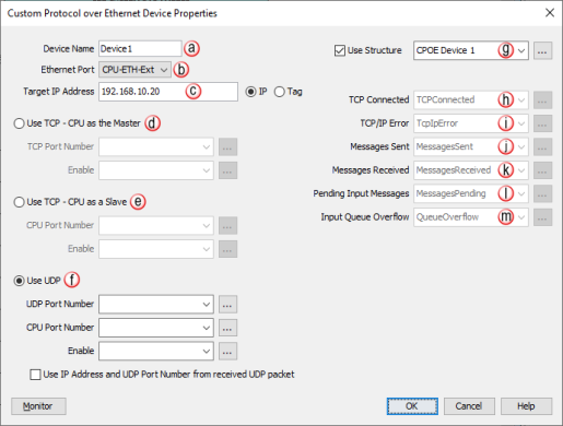
- Device Name: Each Device added to the CPoE window must
contain a unique Device Name that can be referenced if needed through
the Custom Protocol
Ethernet (CPE)
instruction.
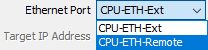
- EtherNet Port: By default
the CPoE Device will use the CPU External Ethernet port (CPU-ETH-Ext).
If the CPU has a second Ethernet port that is user configurable, then,
-
If the CPoE Device is set to Use TCP – CPU as the Master or Use UDP,
it will use whichever port is in the same subnet as Target IP
Address. In the event the Target IP Address is outside of the local
subnets, it will use the port that is in the same subnet as the
Default Gateway to connect to the Target IP Address
-
If the CPoE Device is set to Use TCP – CPU as a Slave, Remote
Ethernet port (CPU-ETH-Remote) can be selected as port the CPoE
Device listens on.
- Target IP Address:
This is where the IP address of the target CPoE device is entered. If
the IP radio button is selected, a valid IP address must be entered in
the adjacent field. If the Tag radio button is selected, a String tag
is required in this field.
- Use TCP - CPU as the Master:
- TCP Port Number:
Enter the TCP port
number of the
Target device as an
integer value or integer tag. Typically, this value will need to
be a value currently not used by another device. TCP Port number
range is 1 to 65535.
- Enable: Enter a
Boolean tag into this field in order to programmatically control
the configured TCP Master connection.
- Use TCP Slave -CPU as a Slave:
- CPU Port Number: Enter
a CPU port number from 1 to 65535 as an integer value or integer
tag that will be used as the source port number for any outgoing
TCP message from the CPU.
- Enable: Enter a
Boolean tag into this field in order to programmatically control
the configured TCP Master connection.
Note: Incoming
messages are processed at one message per scan.
- Use UDP:
- UDP Port Number: Enter
the UDP port number of
the Target device as
an integer value or integer tag. Typically, this value will need
to be a value currently not used by another device.
UDP Port Node range is
1 to 65535.
- CPU Port Number: Enter
a CPU port number from 1 to 65535 as an integer value or integer
tag that will be used as the source port number for any outgoing
UDP message from the CPU.
- Enable: Enter a
Boolean tag into this field in order to programmatically control
the configured UDP connection.
- Use IP Address & UDP Port Number from UDP Read: Will get the IP address & UDP port number from the
mastering device's Ethernet packet
Note: When a
broadcast address is entered (255.255.255.255) & when Use UDP is
selected, the UDP port entry is not required.
Note: Incoming
messages are processed at one message per scan.
- Use Structure: Enables use
of
Structures.
- TCP Connected: The TCP Connected bit indicates that the
TCP connection has been successful. It is sometimes helpful in
troubleshooting CPoE connections to know if the
TCP connection has been successful in order to isolate a
fundamental network connection (IP address issues, TCP port
issues, etc.)
Note: TCP connection is not closed if CPoE end device is
powered down. The Enable tag for each configured device must be disabled
& reenabled to reestablish a TCP connection.
- TCP/IP Error: This string tag will contain an error created
when the TCP connection fails. This tag should be used to help
troubleshoot connections to adapter devices. Below are the possible
errors the string may be populated with:
-
"REJECTED" if the peer rejects the TCP connection.
-
"NO RESPONSE" if the peer does not answer (most likely the peer
does not exit due to offline or wrong IP setting).
- Messages Sent: A numeric tag that contains a count of how many
messages have been sent.
- Messages Received: A numeric tag that contains a count of how
many messages have been received by the specified CPU port.
- Pending Input Messages: This numeric tag contains how many
messages are currently in the queue.
Note: The pending
messages queue will store up to 10 messages. Each enable of the
instruction will get the next available message using a first in first
out method.
- Input Queue Overflow: Boolean tag that turns ON when the
incoming buffer queue is full. Will remain set until the user manually
resets it or it is reset automatically each time the instruction is
enabled.
Note: The
following port numbers are reserved for internal or predefined
functions: 20, 21, 23, 25, 123, 502, 2222, 8877, 8887, 8888, 9999,
11102, 18888, 25425, 28784, and 44818. Additionally, the 10.20.x.x
subnet is reserved internally and cannot be used.