|
|
Topic: P258 |
EtherNet/IP Scanner Configuration |
|
|
|
Topic: P258 |
EtherNet/IP Scanner Configuration |
|
An
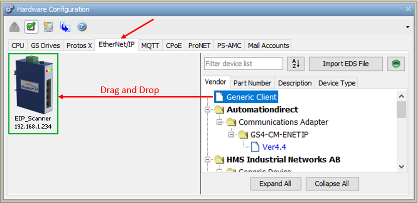
To configure your CPU as an EtherNet/IP Scanner, use the setup tools found in the Hardware Configuration window. The EtherNet/IP options are found under the EtherNet/IP tab of the Hardware Configuration window as shown below. To configure a client device, click and drag (or double-click) a Generic Client or existing EDS File from EDS Library in right-hand column onto the EtherNet/IP palette. The EDS library comes pre-populated with AutomationDirect EtherNet/IP Adapter devices. To add new EDS files, see the EtherNet/IP EDS file import help topic.
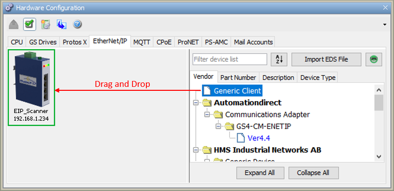
You can create an EtherNet/IP device via three possible methods:
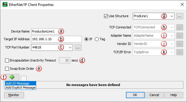
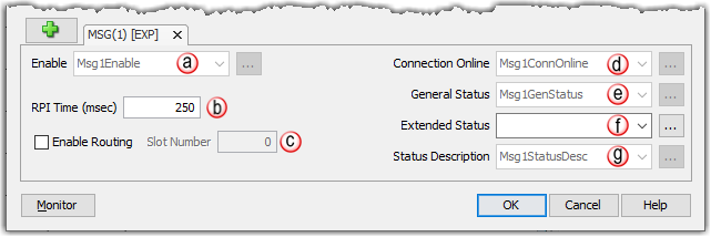
Once a client has been placed on the palette, the following EtherNet/IP Client Properties window will appear.
Note: A maximum number of 4 EtherNet/IP clients is allowed per P1-412 CPU or P1-M412 PLC. All other CPUs and PLCs allow a maximum of 32 EtherNet/IP clients..
Note: TCP keep-alive traffic does not qualify as Encapsulation activity.
The Encapsulation Inactivity Timeout is used to enable TCP socket cleanup (closing) when the defined number of seconds have elapsed with no Encapsulation activity.
Note: Closing of the Encapsulation Session and the reset of the TCP connection does not stop the previously established exchange of I/O messaging data (via the UDP transport protocol).
Note: Device specific connections may also be available from within the menu after importing the EDS file for the target device.
TCP/IP Error: This string tag will contain an error created when the TCP connection fails. This tag should be used to help troubleshoot connections to adapter devices. Below are the possible errors the string may be populated with.
(Shown using Structures)
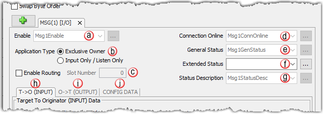
Application Type:
Note: Consult the server's documentation for the maximum message size in bytes to determine how many array elements are required. If the array size in bytes is smaller than the actual message size the remaining bytes will be discarded. Each extended status will be stored in their own array element.
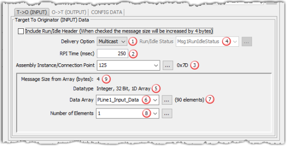
- Delivery Option: Some adapter devices can be configured to Multicast their input data on the network or Unicast their input data back to the Originator (scanner) device. Some devices only support multicasting of input data. In some situations where the Adapter device supports both, it may be desired to have multiple devices consuming this data and it is more efficient to Multicast. Unicast tends to be more ‘quiet’ on most networks.
RPI Time (msec): RPI stands for Requested Packet Interval. This establishes how often the input data (in milliseconds) will be sent back to the Scanner from the Adapter device. The smaller the value configured in this field, the more resource intensive it will be for both devices. See the EtherNet/IP Performance Calculation section for information on RPI restrictions.
Connection Point: This field is where the Connection Point parameter for the desired input data block of the Adapter device is entered. This value is specific for the Adapter and must be ascertained from the manufacturer’s documentation of that device when not using its EDS file. The value is entered in decimal format or as an integer tag. There is a hexadecimal representation to the right of the entry field for convenience as many devices specify this parameter in that format.
Run/Idle Header & Status: Some Adapter devices support run/idle status for the T->O direction. The Include Run/Idle Header check box enables the Run/Idle Status field and increases the message size by 4 bytes. Run/Idle Status is a Boolean tag (On = Run; Off = Idle) indicating the status of the Adapter device.
Datatype: This is a read-only field that displays the data type of the selected Data Array. This helps to determine the size of the input data that needs to be configured in order to match the Adapter configuration.
Note: The number of bytes being requested will need to match the Adapter configuration or an error will be returned.
Data Array: The array specified in this field will hold the input data received from the Adapter device. The size of the array must be sufficient to support the specified Number of Elements being requested. If the Number of Elements requested exceeds the array size, a warning will be given to correct this. Only single dimension arrays can be specified for this field.
This is a read-only field that displays the number of elements in the specified Data Array.
Number of Elements: This is an entry field to specify the number of array elements that will hold the input data returned from the Adapter device. The value is entered in decimal format or it can be an integer tag.
Message Size (bytes): This is a read-only field that displays the size of the data configured by the specified array data type and the Number of Elements field in bytes.
Data Type Number of Elements Message Size (Bytes) Integer 8-Bit 100 100 Integer 16-Bit 100 200 Integer 32-Bit 100 400

- Include Status Header: Adds 4 bytes to the message
RPI Time (msec): RPI stands for Requested Packet Interval. This establishes how often the output data (in milliseconds) will be sent to the Adapter from the CPU. The smaller the value configured in this field, the more resource intensive it will be for both devices. See the EtherNet/IP Performance Calculation section for information on RPI restrictions.
Note: The P-Series cannot produce output data any faster than the current scan time.
Assembly Instance / Connection Point: This field is where the Connection Point parameter for the desired output data block of the Adapter device is entered. This value is specific for the Adapter and must be ascertained from the manufacturer’s documentation of that device when not using its EDS file. The value is entered in decimal format or as an integer tag. There is a hexadecimal representation to the right of the entry field for convenience, as many devices specify this parameter in hexadecimal format.
Datatype: This is a read-only field that displays the data type of the selected Data Array. This helps to determine the size of the output data that needs to be configured in order to match the Adapter configuration.
Note: The number of bytes being requested will need to match the Adapter configuration or an error will be returned.
Data Array: The array specified in this field will hold the output data being sent to the Adapter device. The size of the array must be sufficient to support the specified Number of Elements being requested. If the Number of Elements requested exceeds the array size, a warning will be given to correct this. Only single dimension arrays can be specified for this field.
This is a read-only field that displays the number of elements in the specified Data Array.
Number of Elements:This is an entry field to specify the number of array elements that will hold the output data sent to the Adapter device. The value is entered in decimal format or can be an integer tag.
Data Type Number of Elements Message Size (Bytes) Integer 8-Bit 100 100 Integer 16-Bit 100 200 Integer 32-Bit 100 400
Message Size from Array (bytes): This is a read-only field that displays the size of the data configured by the specified array data type and the Number of Elements field in bytes. If a tag is used in the Number of Elements field, the value in this field will be automatically updated to reflect the Message Size in bytes..
Data Type Number of Elements Message Size (Bytes) Integer 8-Bit 100 100 Integer 16-Bit 100 200 Integer 32-Bit 100 400
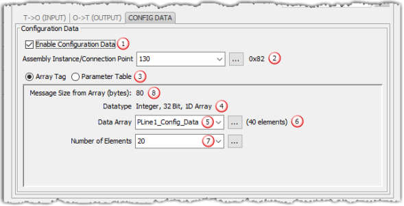
Enable Configuration Data: The configuration data can be selectively chosen for each IO Message setup (CIP Forward Open). Enable this checkbox if configuration data is desired for the Adapter device.
- Assemble Instance/Connection Point: This field is where the Connection Point parameter for the desired configuration data block of the Adapter device is entered. This value is specific for the Adapter and must be ascertained from the manufacturer’s documentation of that device when not using its EDS file. The value is entered in decimal format or as an integer tag. There is a hexadecimal representation to the right of the entry field for convenience as many devices specify this parameter in that format.
- Array Tag: See Data Array below for additional details.
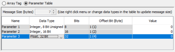
Parameter Table: Allows user to enter a data type per parameter in table format. Right click to Add or Delete parameter(s). If Add Parameters is chosen, then enter the number of parameters needed for the configuration.
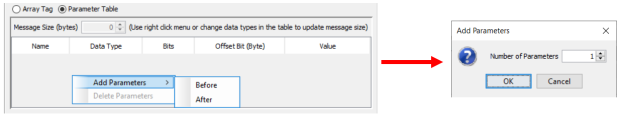
Once the number of parameters is configured, choose a data type and value for each entry.
- Datatype: This is a read-only field that displays the data type of the selected Data Array. This helps to determine the size of the output data that needs to be configured in order to match the Adapter configuration.
- Data Array: The array specified in this field will hold the configuration data being sent to the Adapter device. The size of the array must be sufficient to support the specified Number of Elements being requested. If the Number of Elements requested exceeds the array size, a warning will be given to correct this. Only single dimension arrays can be specified for this field.
- This is a read-only field that displays the number of elements in the specified Data Array
- Number of Elements: This is an entry field to specify the number of array elements that will hold the configuration data being sent to the Adapter device. The value is entered in decimal format or it can be an integer tag.
- Message Size (bytes): This is a read-only field that displays the size of the data configured by the specified array data type and the Number of Elements field in bytes. The Message Size is limited to 400 bytes.
Data Type Number of Elements Message Size (Bytes) Integer 8-Bit 100 100 Integer 16-Bit 100 200 Integer 32-Bit 100 400
Note: The number of bytes being requested will need to match the Adapter configuration or an error will be returned.
Note: Device specific connections created from an EDS import may have preset parameter values, range limitations, and / or inhibited fields.
The Explicit Message setup is intended to establish a Connected Explicit Message connection (Class 3). The Explicit Message setup in the EtherNet/IP Client Properties is used in conjunction with an EtherNet/IP Explicit Message Instruction in the ladder code.
Note: If an unconnected Explicit Message is desired, no Explicit Message setup is required in the EtherNet/IP Client Properties dialog, only the general properties are required (at the top).
(Shown using Structures)
Enable: Enter a Boolean tag into this field in order to programmatically control the configured Connected Explicit Message connection.
Note: Consult the server's documentation for the maximum message size in bytes to determine how many array elements are required. If the array size in bytes is smaller than the actual message size the remaining bytes will be discarded. Each extended status will be stored in their own array element.
If the RPI is modified from the default of 250, the following warning will be displayed. Since the CPU supports a maximum of 5120 EtherNet/IP packets per second, you will need to ensure this maximum is not exceeded by using the formula below:
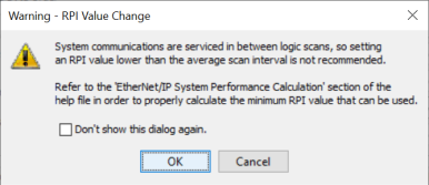
Formula: Number of Connections *(2 *(1/RPI)) <= 5120
Note: RPI is in units of milliseconds (msec).
Example: If you are using 128 Connections (Max. # of Connections = 32 * 4 connections) and all connections are set to 50 msec RPI.
Example Formula: 128*(2*(1/.050) = 5120
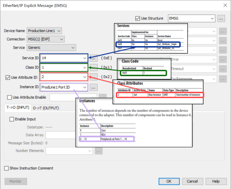
The example below shows how a Class 3 Explicit Message might be accomplished from a 3rd party device (Allen Bradley PLC). As you can see the Input Data must be retrieved in 1 connection or message and the output data in another. Remember that Class 3 messaging is not as efficient in protocol messaging as Class 1 but it does allow for granular control.
Note: In this example, size configuration is not shown on the Scanner side. The tag created for the Destination must be large enough to contain the data requested (shown with dashed boxes).
This example shows how to connect the Productivity Suite Scanner function to an EtherNet/IP adapter device using Class1 IO Messaging. First, create an EtherNet/IP device in the Hardware Configuration as seen below:
Configure the parameters to match the settings of the Adapter device. The image below shows the setup of the Input data. The size, in this case, is dynamic to the configuration of the device. For this particular example, we configured the device in a manner that allows it to publish 394 bytes of data for Input. Many devices will have a fixed configuration, this can found in the manufacturer’s documentation.
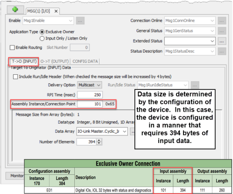
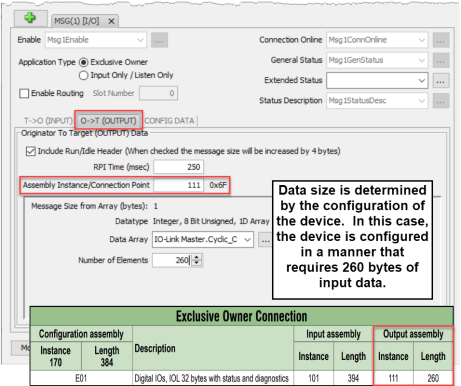
The Output data must also be configured. Its data is also dynamic based upon the configuration. In our example, we configured the device in a manner that caused it to require 260 bytes of Output data.
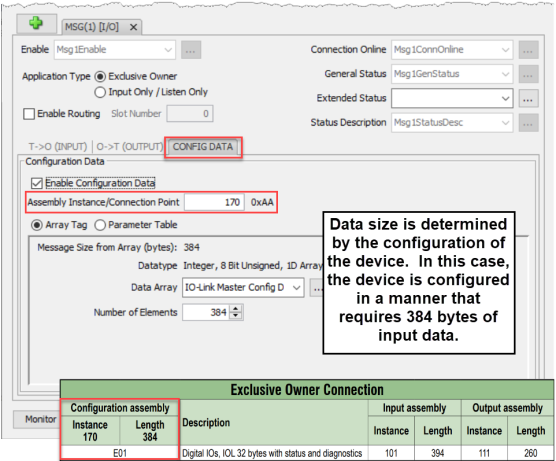
The image below shows the setup for the Configuration data. The Configuration data, for most devices, is a fixed size. Some devices will require that the Configuration data Connection Point be included in the Forward Open message (as shown below) even if the size is 0. Some devices will require that the Configuration data Connection Point not be in the Forward Open and the checkbox option in the image below would need to be deselected.
The following example shows how to connect the Productivity Suite Scanner function to an EtherNet/IP adapter device using Class 3 Explicit Messaging. As with IO Messaging, an EtherNet/IP device must be created in the Hardware Configuration as seen below:

![]()
Explicit Messages can be performed in 2 ways: Unconnected or Connected (Class 3). The advantage of using Unconnected messaging is it allows more discrete control of each request. The disadvantage of Unconnected messaging is that Unconnected messages have a lower priority and will take longer to get serviced on some devices. Connected messages get serviced faster since there is a connection established to the device. If Connected messaging is desired, create an Explicit Message tab as shown in the image above. If Unconnected messaging is desired, do not create an Explicit Message tab. Only fill out the information in the upper portion of the EtherNet/IP Client Properties window.
Once the desired parameters have been entered, the device may now be referenced in the Explicit Message Instruction. If Unconnected messaging has been selected, choose the Unconnected MSG option in the Connection drop down box. If Connected messaging has been selected, choose the Explicit Message that was configured in the EtherNet/IP Client Properties window in the Connection drop down box. The rest of the settings should be matched to the specifications documented by the manufacturer. An example for requesting the Identity of a device is shown below. The data array configured for this function must be sufficient in size to hold the returned data from the device for this object. Data can also be written to the device if it supports an object for this purpose. If data is being written, enable the Output selection and specify the data array and size required by that device’s object.