|
|
Topic: P195 |
Communications Port Configuration |
|
|
|
Topic: P195 |
Communications Port Configuration |
|
The Communications Port Configuration for any module containing communications ports is accessed from the Hardware Configuration window. For example, to access the P3-550 communications port configuration, first select the Local Base Group from the Hardware Configuration window by double left-clicking the Local Base Group or by right-clicking the Local Base Group and selecting Open from the drop down menu as seen below.
Then select the P3-550 by double left-clicking the CPU or by right-clicking the CPU and selecting Open from the drop down list. This will display the P3-550 configuration window.
The P3-550 window will open as shown below. Although the following descriptions will focus on the P3-550 communications ports, the settings also apply to any other module containing these ports.
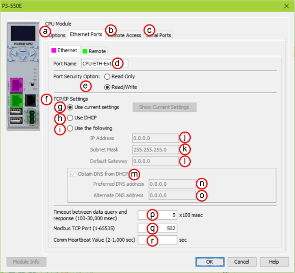
Ethernet Ports: There are two 10/100Base-T Ethernet ports on most Productivity CPU's. P3-530 and P1-540 CPUs only have the External Ethernet port.
Note: Two CPU Remote I/O networks cannot co-exist on the same LAN.
- The Settings may be entered manually in the Choose CPU tool in the Productivity Suite programming software. This allows the user to make changes to the IP to allow connection by the computer running the Productivity Suite programming software. Changes are sent using Multicast Messages.
- The Settings can be saved as part of the project. This must be Enabled in the P3-550 Hardware Configuration Settings by selecting Use the Following (discussed on Item f below). If handled this way, the Settings stored in the project will take effect at Project Transfer and at boot up only. The Settings may be changed after boot up.
Note: If the CPU is set to use DHCP for it's IP Settings it cannot, in all likelihood, be used as a Modbus TCP Server.
Note: Other names for a DNS server include name server, nameserver, and domain name system server.
Ethernet Ports Tab: Click on this Tab to go to the Ethernet Ports Configuration dialog.
Session Timeout: Allows the user to set a specific time limit (1-20 mins.) on inactivity that will close the Web Server connection. If there is no activity between the PC and the Web Server for the specified time limit, the connection will close.
Password Option: Allows the user to set a password for Remote Access using the CPU Data App or access to the Web Server.
When the Serial Ports Tab is selected, the Serial Ports settings are displayed as shown below.
There are two Serial Ports on the Productivity CPUs. Both Ports are capable of Modbus RTU Client (device that initiates communications requests) and Server (device that responds to communications requests) communications. They are also capable of ASCII outgoing strings and incoming strings.

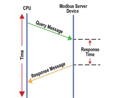

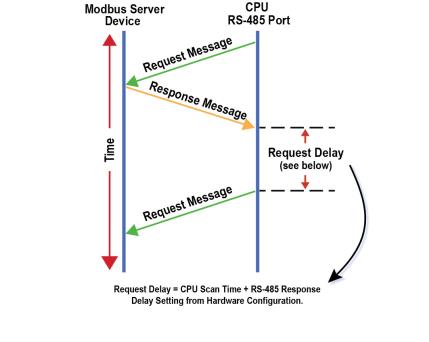
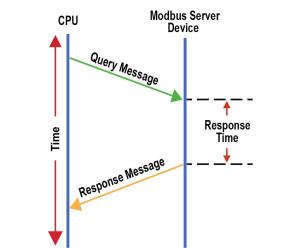
The total Response Time can be up to the Total CPU Scan Time + the Value specified in this field. When using 2-wire RS-485 communications, sometimes Echoes can occur since both devices use the same differential signal pair to send and receive.
- If acting as a Server, upon receiving a Modbus Request, the CPU will wait for the time period specified in this field before sending a Response. This can be used with slow clients that need extra time to change from sending to receiving.
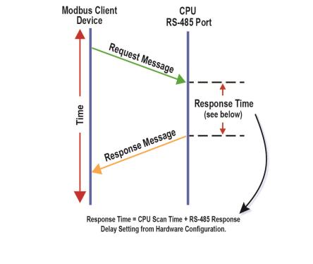
- If acting as a Client, after receiving a Modbus Response, the CPU will wait for the time period specified in this field before sending another Request. This can be used to delay request messages in order to give extra time for slow server devices.