|
|
Topic: P200 |
Communications Remote I/O, GS-Drives and Protos X Field I/O |
|
|
|
Topic: P200 |
Communications Remote I/O, GS-Drives and Protos X Field I/O |
|
It is important to understand that only one Remote I/O network can be on an unmanaged switch. If two or more Remote I/O networks are mixed into the same physical LAN (local area network), duplicate IP addressing will occur and the system will not function properly. Multiple Remote I/O networks can be used on a managed switch using the VLAN feature to create a virtual separation of the different networks, but multicasting messages are necessary for the network to function properly. Care must be taken when designing a system this way (using a managed switch).
Even if only one Remote I/O network is being used in a facility, it is strongly recommended to keep it on a dedicated network, physically isolated from other networks. As mentioned above, the Productivity Suite Remote I/O network makes use of multi-casting messages and many devices will not function properly in this situation.
The GS Drive configuration does not use multicasting in its setup but there are some initial UDP broadcast messages that occur upon discovery when initiated from the software and at power up. This should be considered if installing the GS Drive network with other devices.
The Productivity Suite Remote I/O is very easy to configure. Each Remote Slave module’s address is set by rotary switches on the front of the module or on the base The X1 switch is used to set the least significant digit and the X10 switch is used to set the most significant digit. So if the X10 switch were set to 2 and the X1 switch were set to four, the Slave Address of that module would be 24. Valid addresses are 01-99. 00 is not valid. Each slave module must have a unique address and up to 16 slave units (P3), eight slave units (P2), or four slave units (P1), are allowed on a single system. Of the remote slaves, P2 and P3 support four PS-AMC modules, and P1 supports one PS-AMC module.
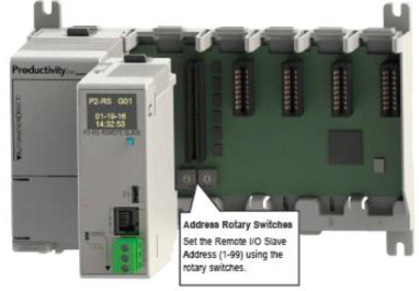
The address rotary switches are only read by the P3-RS/RX,P2-RS, and P1-RX at power up. Power must be cycled after an address change for it to take effect. Connect a straight through (patch) Ethernet cable from the front of the P3-RS/RX or P1-RX or the bottom of the P2-RS module to an Ethernet switch. Connect a straight through cable from the CPU Local Ethernet (Remote I/O) port (lower Ethernet port (P3 and P1 CPUs) or bottom back (P2 CPUs)) to the same switch. Open up the Productivity Suite Programming software and connect to the CPU. Once the software is connected, open Hardware Configuration. Select the “Read Configuration” button in the upper left hand corner of this dialog and the CPU will automatically discover the slave modules connected to the switch and return all found P3-RS/RX (P3 only) or P2-RS (P2 only), or P1-RX (P2 and P1 only) modules and their configurations (bases and I/O modules).
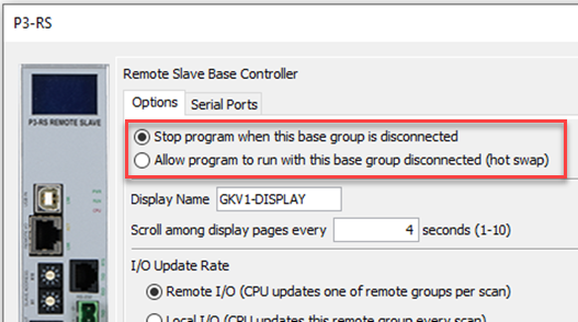
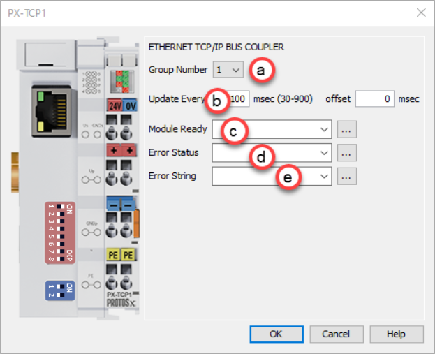
There are two fields that can be configured in regards to connectivity to the slave modules. The above diagram shows the CPU hardware configuration popup where these settings can be found.
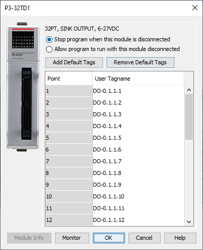
CAUTION: If a timeout occurs and a module within a P3-RS/RX, P2-RS, or P1-RX base or expansion base connected to the master has the “Stop program when this base group is disconnected” selection enabled, the CPU will go out of run mode and a critical error will be generated.
CAUTION: If a timeout occurs and the P3-RS/RX module has the “Automatic Remote Base Group Detection” selection enabled, the CPU will go out of run mode and a critical error will be generated.
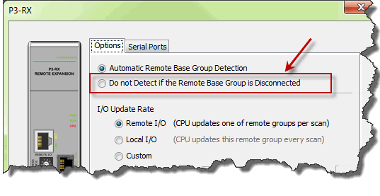
- If a timeout occurs but all of the modules within the P3-RS/RX or P2-RS base or expansion bases (P3 only) connected to the P3-RS/RX or P2-RS have the No Verification and EnableHot Swapselection enabled and the P3-RS/RX or P2-RS module has the “Do not Detect if the Remote Base Group is Disconnected” selection enabled, the CPU will remain in Run and a non-critical error will be generated.
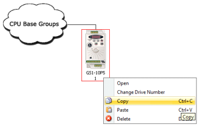
GS Drive connections are set up in a similar manner as the Remote Slaves. Set a unique address for each GS-EDRV100 using its DIP switches. Or set the DIP switches to 0 and select the address using NetEdit (free download at AutomationDirect.com). 01-99 are valid addresses for a GS-EDRV100 in a Productivity Suite system. Since the DIP switch settings can only represent 01-63, setting a GS-EDRV100 to address 64 or higher must be done using NetEdit.
GS Drive Ethernet connections are set up in a similar manner as the Remove Slaves. Set a unique address for each GS drive by setting the last octet of the IP address assigned to the communication option module. The IP address can be set either by using the keypad on the GS drive or by using GSoft2 software. To configure control via the Communications option module. The following GS device parameters must be set as shown:
Parameter 3.00 = 5 1st source of operation command = Comm Card, keypad STOP is enabled
Parameter 4.00 = 4 1st source of frequency command = Comm Card
Parameter P00.21 = 5 1st source of operation command = Comm Card
Parameter P00.20 = 8 1st source of frequency command = Comm Card
1. P9.74 must be set to 2 before attempting to discover via the Hardware Configuration button. If the drive is ever defaulted, it will have to be manually set again.
2. Lowest octet for the IP address (P9.79) must be set to a value in the range of 1 – 64 and not conflict with any other GS Drive node numbers. After setting the value in P9.79, you need to change P9.91 to a value of 2.
3. The GS20 and GS30 drive properties default to a 60Hz configuration. If you are resetting factory default to 50Hz, you should consider changes to the following parameters: P1.00, P1.01, P1.35, P1.52, P1.53, P1.54, P1.62, P1.63, P2.22, P2.24, P2.25, P2.34, P2.58 and P2.83.
4. Keep in mind that due to the very large parameter set for GS20 and GS30 drives, the drive will take several seconds to be Ready after the PLC goes into Run.
Note: The last octet of the IP address must be between 01-99.
Note: Can't have last octet same as GS1, 2, or 3 same node id.
Note: EtherNet/IP (GS4-CM-ENETIP) Communication module is not supported for auto discovery. When using GS20A-CM-ENETIP, it is imperative that P9.74 is set to 2 (that is, Modbus TCP mode) before attempting to add it to a Productivity system. If the drive is defaulted, P9.74 will need to be manually re-set to 2.
After the GS-EDRV100 modules’ addresses have been set, be sure to connect the serial cable that comes with the GS-EDRV100 to the GS-Drive serial port. The GS-EDRV100 will automatically configure the GS-Drive serial port to the correct settings. Once the GS-EDRV100 is properly addressed and connected to the GS-Drive, connect a straight through (patch) Ethernet cable from the Ethernet port of the GS-EDRV100 to an Ethernet switch. Connect a straight through cable from the P-Series CPU Local Ethernet Port (Remote I/O) to the same switch.
Open the Productivity Suite Programming software and go online with the P-Series CPU. Select Setup and then Hardware Configuration. Select the “Read Configuration” button in the upper left hand corner of this dialog and the P-Series CPU will automatically discover all of the GS-EDRV100s connected to the switch and display all found GS-Drives.
After the GS drive IP address has been set, be sure to connect from the GS-Drive Ethernet Port on the Modbus TCP Communications Options Module (GS4-CM-MODTCP) or for GS20 (GS20A-CM_ENETUO1) and GS30 (GS30A-CM-ENETIP1) to an Ethernet Switch. Connect an Ethernet cable from the P-Series CPU Local Ethernet Port (Remote I/O) to the same switch.
Open the Productivity Suite Programming software and go online with the P-Series CPU. Select Setup and then Hardware Configuration. Select the “Read Configuration” button in the upper left hand corner of this dialog and the P-Series CPU will automatically discover all of the GS drives connected to the switch and display all found GS-drives.
Once the drives have been discovered, the configuration of each drive can be read and written from the programming software.
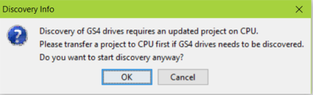
Note: If attempting to auto discover a GS4 drive on a new CPU or a CPU with 3.3 or older software, a 3.4 project must be loaded first.
The option of Manually adding drives and configuring the drive parameter settings can be done prior to the actual installation of the GS Drives, thus allowing a user to download these drive parameters to each drive once equipment is installed, which will in turn eliminate the time consuming Manual set up of each drive.
To allow the P-Series CPU to automatically write the drive parameters on each CPU project transfer and when the CPU is powered up, a setting must be configured in the P-Series CPU project. Go to Tools and Options and select the “Project Transfer” tab. Select the “Transfer GS drive configuration” as shown below. Drive parameters are ONLY transferred to the GS Drive at project transfer or at boot up of the CPU.
To monitor the status of the connection between the P-Series CPU and the GS-EDRV100 (GS1,2,3) and/or Modbus TCP (GS4) modules, use the status bits of the GS Read and GS Write instructions as shown below. If a Timeout occurs or an error is received, this can be monitored in the ladder code and appropriate action can be taken.
The Communications Heartbeat function is configured differently for the GS Drives than the Remote Slaves. Primarily because, as mentioned previously, there are two possible communication paths that could be lost:
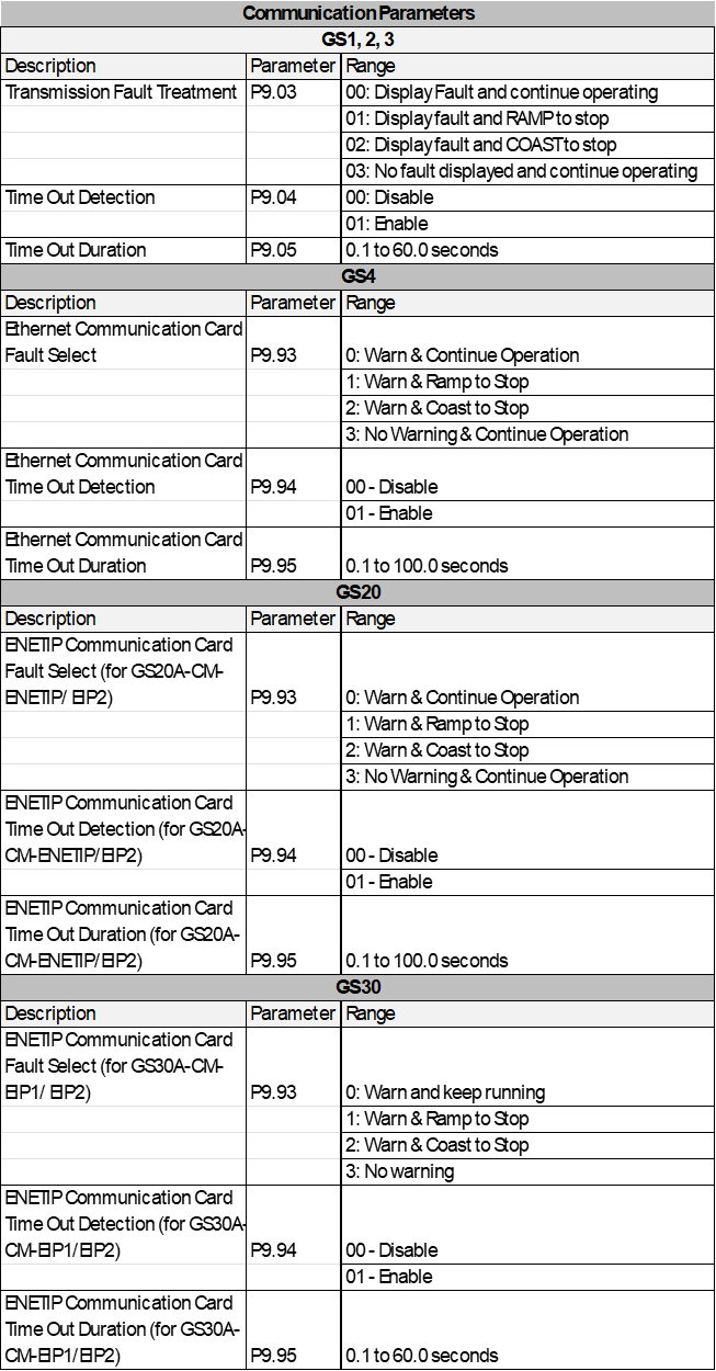
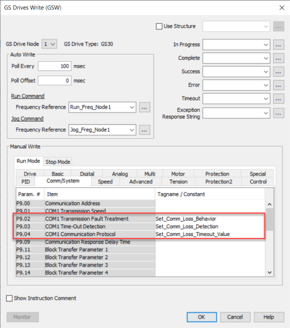
To configure the GS-EDRV100 and GS Drive to detect and react to loss of communications, three parameters should be configured appropriately in the drive.
As shown below, parameter P9.03 determines what the drive will do when it detects loss of communications. Parameter P9.04 enables the transmission loss detection feature. Parameter P9.05 determines the amount of time the drive will wait for a transmission before assuming that the link is lost and react according to how parameter P9.03 is configured.
The GS-EDRV100 or Modbus TCP module reads these configured parameters and if they are configured for detecting communications loss, it will also monitor for loss of communications on the Ethernet side. If communications are lost on the Ethernet side, the GS-EDRV100 or Modbus TCP module will shut down the GS Drive.
It is very important to note that if the communications loss feature is enabled; either a GS Drive Read or GS Drive Write instruction needs to be configured to communicate to the GS-EDRV100 and GS Drive at a poll rate that will prevent the GS-EDRV100 (GS1, 2, 3) or Modbus TCP module (GS4) or ENETIP/Modbus module (GS20 & GS30) and GS Drive from detecting a loss of communication.
There is also a parameter (P22.01) that can be monitored to check the health of the serial connection between the GS-EDRV100 and the GS Drive. This parameter can be monitored in the ladder code and appropriate action taken if serial communications loss is detected.

Note: If there are no active GS instructions, the ready bit may not be reset even if the ethernet cable is disconnected.
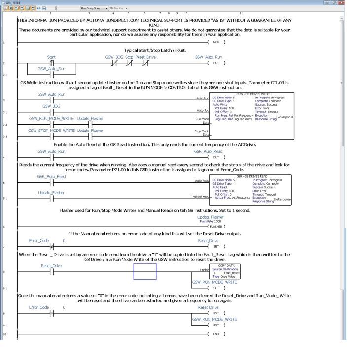
When using the Remote IO functionality and GSW/GSR instruction to the GS4 drives the following logic must be used to reset the GS4 Drive after an error has occurred.
Note: This is required when parameters 9.93, 9.94, and 9.95 of the GS4 Drive have been set to detect a communications loss when used with the GS4-CM-MODTCP module.
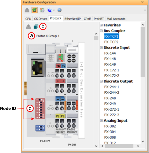
The Protos X Field I/O is very easy to configure. Each PX-TCP1 or PX-TCP2 P module’s address is set by dip switches on the front of the module. The dip switches are used to set the node ID. Valid addresses are 01-99. 00 is not valid. Each slave module must have a unique address and up to 4 bus couplers are allowed on a single system.
Note: Reference PX-TCP1 or 2 insert or hardware manual for further details.
Note: Both PX-TCP1 and TCP2 must have an IP address 10.20.100.x (last octet is set by dip switches) and subnet mask 255.255.0.0 when placed on Remote I/O port. These are the default settings out of the box.
Note: Limitation of up to (32) terminals and (4) Bus couplers allowed per system.
With the CPU Online, open the Hardware Configuration window as described above and select the Read Configuration button. During the Read Configuration process the following will happen:
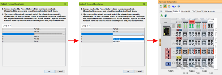
Note: PX-902 and 903 bus expansion couplers can't be auto discovered. Therefore, you must manually add to your configuration.
Manual configuration allows a user to add, move, or remove modules to and from the hardware configuration.
Note: No hot swap option available. Therefore, configuration must match actual hardware or error will occur.
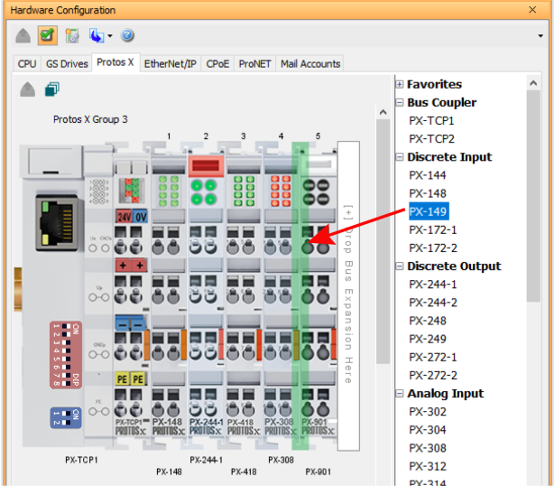
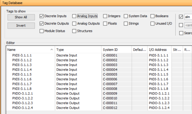
Protos X discrete or analog I/O will be prefixed with PX. All Protos X remote I/O will have system ID's assigned to their corresponding discrete I/O data type.