|
|
Topic: P330 |
Modbus Device and Productivity CPU Modbus Device Configuration |
|
|
|
Topic: P330 |
Modbus Device and Productivity CPU Modbus Device Configuration |
|
Modbus is a common protocol for industrial communication. Modbus TCP uses Ethernet as a transport layer, while Modbus RTU primarily uses RS-485, though it can support other serial modes. Productivity supports both Modbus TCP and Modbus RTU. Next-generation Productivity CPUs (P2-622 and newer) support dynamic addressing for Modbus communications, using Modbus Devices.
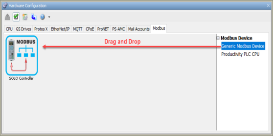
To configure a Modbus Device, use the setup tools found in the Hardware Configuration window. Two device options are available, with different purposes. The Generic Modbus Device is used for any Modbus TCP/RTU device and creates an addressable device for use with theMBUS instruction. The MBUS instruction is similar to the MRX and MWX instructions, but allows for program control of transaction parameters, so instructions can be easily reused. The Productivity PLC CPU option is used for communicating tag values directly between Productivity CPUs using the new NETW instruction, and is most similar to the existing RX and WX instructions.
Select the Modbus Device type desired for the project and double-click or drag and drop to add to the project configuration.
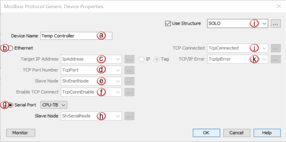
Slave Node: If Ethernet is selected, enter the Target device node. When using Modbus TCP, this value is typically 255 unless interfacing with a protocol converter that forwards Modbus messages. An integer tag can also be selected here if changing the target slave node is required within the program.
Enable TCP Connect:This Boolean must be active to enable a TCP Connection to a Target device.
Slave Node: If Serial is selected, enter the Target device node. An integer tag can also be selected here if changing the target slave node is required within the program.
Use Structure: Select to create a Predefined Structure that contains tags for the instruction elements.
TCP Connected: This Boolean becomes active when an active TCP Connection is present.
TCP/IP Error: This string tag will contain an error created when the TCP connection fails. This tag should be used to help troubleshoot connections to Target devices.
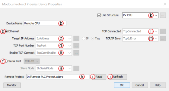
Device Name: Each Productivity PLC CPU added to the Modbus window must contain a unique Device Name that can be selected in the Network Read/Write (NETW) instruction
Ethernet: Select this option if Ethernet is to be used for this device
Target IP Address: If Ethernet is selected, this is where the IP address of the target Productivity CPU is entered. A string tag can also be selected here if changing the target IP address is required within the program
TCP Port Number: If Ethernet is selected, enter the Modbus Server port number of the target Productivity CPU. Typically, this value will need to be 502 as this is the registered TCP port number for the Modbus TCP protocol. An integer tag can also be selected here if changing the target TCP port is required within the program
Enable TCP Connect: This Boolean must be active to enable a TCP Connection to a target device.
Serial Port: Select this option if Modbus RTU is to be used for this device
Slave Node: If Serial is selected, enter the Target device node. An integer tag can also be selected here if changing the target slave node is required within the program.
Remote Project: This is the path and filename of the project to be referenced when reading to or writing from a target Productivity CPU
Read: Select this button to browse to the desired remote project file
Refresh: Select this button to update any tags used in the local project that may have changed in the selected remote project file.
Use Structure: Select to create a Predefined Structure that contains tags for the instruction elements
TCP Connected: This Boolean becomes active when an active TCP Connection is present
TCP/IP Error: This string tag will contain an error created when the TCP Connection fails. This tag should be used to help troubleshoot connections to target devices.