|
|
Topic: P197 |
Communications Ethernet |
|
|
|
Topic: P197 |
Communications Ethernet |
|
When doing TCP/IP and UDP/IP communications, there is a Source Port number and Destination Port number for every message. The Client device must be aware of the Destination Port Number(s) that the Server device is expecting to see and the Server device must listen for this Destination Port number. After the Server device has received the message with the Destination Port Number that it is listening on, it will formulate the return message (if the applications require this) with the Source Port Number from the message sent as its Destination Port Number.
It is important to understand a little about the Port numbering concept because many Ethernet devices, such as routers with firewalls, will block messages with Destination Port numbers that are not configured for that device. Listed below are the default Port Numbers used in the Productivity Suite system. Some of these are configurable, allowing more flexibility when going through routers in many applications.
|
Port |
Port Number (decimal format) |
TCP or UDP |
Configurable |
|
Programming Software CPU Discovery |
8446 & 8888 |
UDP |
No |
|
Programming Software Connection and Project Transfer |
8444 & 9999 |
UDP |
No |
|
Modbus Client Connections (MRX, MWX, RX and WX instructions) |
502 |
TCP |
Yes |
|
Modbus Server Connections |
502 |
TCP |
Yes |
|
GS-Drive Discovery |
28784 |
UDP |
No |
|
GS-Drive Connection |
502 |
TCP |
No |
|
Remote I/O Discovery |
8887 |
UDP |
No |
|
Remote I/O Connection |
8877 |
UDP |
No |
|
Email Instruction |
25 |
TCP |
No |
|
EtherNet/IP |
44818 |
TCP |
Yes |
|
EtherNet/IP |
2222 |
UDP |
No* |
|
MQTT |
1883 |
TCP |
Yes |
|
MQTTS |
8883 & 8884 |
TCP |
Yes |
|
ProNet |
18888 |
UDP |
Yes |
|
SNTP Time Server |
123 |
UDP |
No |
|
* Adapters may choose to respond using another port number. |
|||
IP Addresses (used in conjunction with the Subnet Mask and Default Gateway address) are used for network routing. This allows for easy and logical separation of networks.
It is outside of the scope of this help file to explain how IP Addresses and Subnet masks are configured for actual usage. There are many books, documents and tools (Subnet calculators) on the internet that provide this information. Each facility and network will incorporate their own rules and guidelines for how their networks are to be configured.
For testing and verification purpose, it is recommended that the PC and the CPU be on an isolated Ethernet switch. Configure the PC’s network interface card setting as shown below.
Note: Many system settings on your computer require Administrative privileges. Consult with your IT department for necessary privileges and approvals.
Note: You should record initial settings prior to making any network configuration changes.
Windows 10:
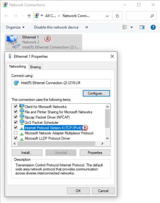
- Right click on the Network interface shown in the Network Connections dialog and select Properties. If there is more than one Network Interface on the PC, be sure to choose the one connected to the Ethernet Switch with the CPU on it.
From the Properties window, highlight the Internet Protocol Version 4 (TCP/IPv4) selection and click on Properties
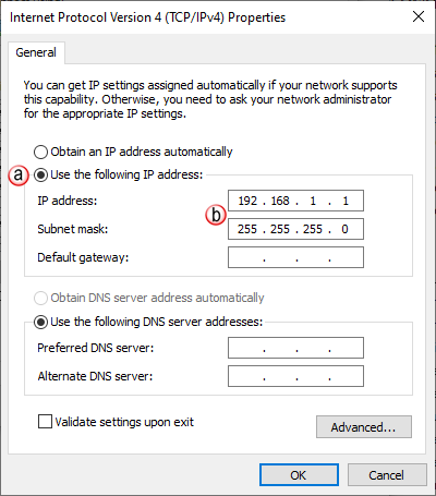
- In the Properties window, select Use the following IP address.
- Enter an IP Address of 192.168.1.1 and Subnet Mask 255.255.255.0 and select OK. Select OK again or Close on the Local Area Connection Properties window.
Now configure the CPU’s network IP setting as shown below.
- Click to highlight the CPU connected to the Ethernet switch.
- Select the “Change CPU IP/Name" button.
- Enter an IP Address of 192.168.1.2 and Subnet Mask 255.255.0.0 for the CPU’s network IP setting and select OK.
The CPU is now configured with the correct IP Address for connectivity with the PC. The IP Address and Subnet Mask settings will very likely differ from what will be used in the actual application. Consult the Network Administrator of the facility where the CPU will be installed to get the appropriate settings for that network.
When performing communications over TCP, a Connection must be established before the applications can transfer data. The connection is typically maintained until the application decides that the connection is no longer needed and then the connection will be severed. Frequent connects and disconnects are not efficient for the Client or the Server and can add unnecessary network traffic. But maintaining connections needlessly is also costly to the Client and Server in terms of processing and memory so this should also be avoided.
The CPU allows user control of Client connections through enabling and disabling the rungs containing Modbus and Network instructions. The MRX, MWX, RX and WX instructions have two options for sending messages: Automatic Poll and Manual Poll.
Automatic Poll sends out messages at a specified rate. Enabling the instruction performs a TCP connect with the Server device. Once the connection is established, the instruction messages are sent at the rate entered in the poll rate field. This continues until the instruction is disabled. The TCP connection will automatically be severed five seconds after the instruction is disabled.
Manual Poll sends out a message each time the instruction is enabled. Enabling the instruction performs a TCP connect with the Server device and sends the message one time. The TCP connection will automatically be severed five seconds after receiving the reply from the Server device. If the instruction gets another positive edge enable within the five seconds, the message will be sent and the disconnect of the TCP connection will be delayed by an additional five seconds.
To determine the total number of Modbus messages that can be sent per second (Ethernet throughput), use the following calculation:
Number of Modbus Masters/Slaves = 8
'Peak Scan Interval' System Tag = 10 msec.
8 x 10 msec (100 scans) = 800 messages per second
Note: The number and size of the tags used in a specific Modbus message will increase the scan time, thus affecting the overall throughput.