|
|
Topic: P193 |
Communications Connectivity |
|
|
|
Topic: P193 |
Communications Connectivity |
|
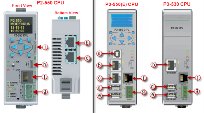
The AutomationDirect P-Series CPUs are provided with several Communications Ports. Each of these ports are described in the sections below. The Communication Ports are:
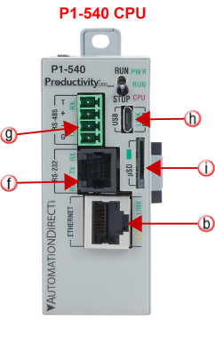
Note: The USB IN port is NOT compatible with older 1.0/1.1 full speed USB devices.
- Connection to a PC running the Productivity Suite programming software.
- Modbus TCP Client connections (Modbus requests sent from the CPU).
- Modbus TCP Server connections (Modbus requests received by the CPU).
- Outgoing Email.
- EtherNet/IP, Scanner/Client and Adapter/Server connections (excludes P3-530).
- MQTT, ProNET, and CPoE (Custom Protocol over Ethernet).
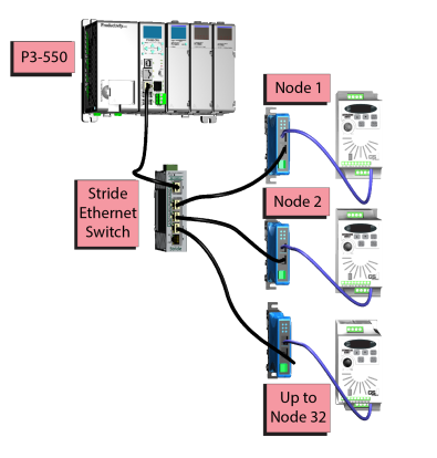
Modbus TCP Client connections: The CPU can connect to 32 Modbus TCP server devices concurrently by means of communications instructions in the ladder program (MRX, MWX, RX, WX). It is possible to connect to more than 32 Modbus TCP server devices, but not concurrently.
This is accomplished by having communications instructions for more than 32 devices in the ladder program and controlling the enabling and disabling of the instructions so that only 32 devices are enabled at a given time. To connect to non Productivity Suite devices, use the MRX (Modbus Read) and MWX (Modbus Write) instructions. To connect to other P-Series CPUs, use the RX (Network Read) and WX (Network Write) instructions.
The greatest difference in the RX versus the MRX is that with the RX, the Tag Name in the target CPU can be referenced directly and does not need a corresponding Modbus address. The way this is accomplished is by mapping local and remote tagnames together within the local CPU's RX instruction. Once the instruction is set up to read a remote project, the "Tags of Remote Project" or "Array Tags of Remote Project" drop down lists will be accessible. Map the Tag of the Remote project to a Tag in the Local project to read this data.
Modbus TCP Server connections: The CPU can serve data back to 32 Modbus TCP Client devices concurrently. If 32 Modbus TCP Client devices are connected to CPU, then any new TCP connection requests will be denied until one of the existing 32 devices drops its connection. If the Client device connecting to the CPU is not a Productivity Suite device, then a Modbus address must be assigned to the tag that is being requested. This is done in the Tag Database window. If the device connecting to the CPU is another P-Series C or C-More panel, no Modbus address is required. See Communications Port Configuration for port configuration, Communications Connectivity for connection information and Communications Ethernet for Ethernet set up.
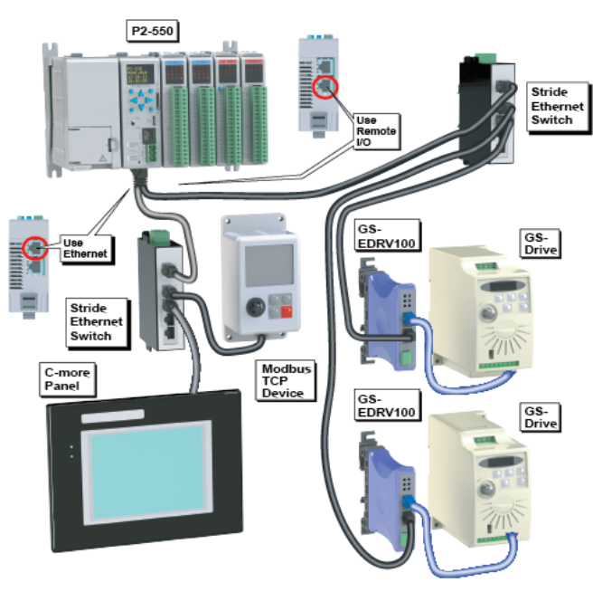
Note: The P2-622 CPU allows the Remote I/O port to be user defined. If the Remote I/O port is user defined, it will function in the same way as the External Ethernet port and will no longer support Remote I/O such as Remote Slaves, AMC modules, Protos X modules, or GS drives. See the P2-622 CPU Module Configuration topic for more details on the Remote I/O port configuration.
Remote Slaves: The P3-550(E) can connect with up to 16 P3-RS/Rand the P2-550 will auto detect allP2-RS units that are configured with unique station addresses (by means of two rotary switches on the front of the module (P3) or on the base (P2). The configuration can be managed in the Hardware Configuration in the Productivity Suite Programming Software. See Communications Remote I/O and GS Drives for configuration information and Communications Connectivity for connection information.
GS Drive Devices: The P-Series CPU can connect to up to 32 (P3) or 16 (P2) GS Drive Communication Modules. The P-Series will auto detect all GS drive communication modules that have a unique address as configured by the bank of dip switches on the module or using the last octet of IP Address for the GS4, GS20, and GS30 communications modules. The configuration can be managed in the Hardware Configuration in the Productivity Suite programming software. See Communications Remote I/O and GS Drives for configuration information and Communications Connectivity for connection information.
Multiple Remote I/O networks
can be used on a managed switch using the
VLAN feature to create a
virtual separation of the different networks, but multicasting messages
are necessary for the network to function properly. Care must be taken
when designing a system this way (using a managed switch).
Even if only one
Remote I/O network is being
used in a facility, it is strongly recommended to keep it on a dedicated
network, physically isolated from other networks. As mentioned above,
the
P-Series Remote I/O network
makes use of multicasting messages and many devices will not function
properly in this situation. The
GS Drive configuration does
not use multicasting in its setup but there are some initial
UDP broadcast messages that
occur upon discovery when initiated from the software and at power up.
This should be considered if installing the
GS Drive network with other
devices.
Note: The USB OUT port is NOT compatible with older 1.0/1.1 full speed USB devices.
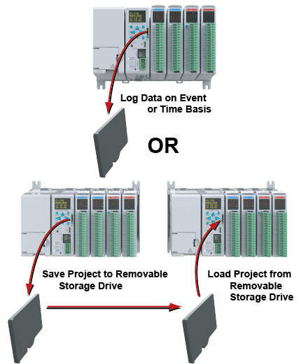
Project Transfer: For security, this feature is disabled by default when creating a new project. It can be enabled in the Hardware Configuration panel for the P-Series. Once enabled, projects may be transferred between a CPU and Removable Storage Device, or between a Removable Storage Device and PC. Files stored on the Removable Storage Device by a P-Series or the Productivity Suite programming software are stored under a default name, so only one project may be handled at a time on a Removable Storage Device. Existing projects on the Removable Storage Device will be overwritten without a prompt.
Data Logging: The Data Logger tool allows setup of periodic or event-based data logging of tag and System Errors to the Removable Storage Drive. Data Logger setup is accessed under the Monitor & Debug Menu. See Communications Connectivity for more information.
Note: P Series CPUs ONLY support up to a 32GB FAT formatted USB pen drive (P3 Series) or MicroSD card (P2 Series).
Caution: This port is ONLY for Expansion I/O. The signal pins on this port are NOT standard USB. DO NOT USE A USB REPEATER TO EXTEND THE RANGE OF THIS PORT. SeeCommunications Connectivity for more information.
P3-EX Expansion Network
- Modbus RTU Master connections.
- Modbus RTU Slave connections.
- ASCII Incoming and Outgoing communications.
- Custom Protocol Incoming and Outgoing communications.
Modbus RTU Master connections: The RS-232 port is intended to be used for point-to-point connections but it is possible to connect up to 128 devices on a network if a RS-232 to RS-485/422 converter is connected to the port (such as a FA-ISOCON). This is accomplished by using the communications instructions in the ladder project (MRX, MWXRXWX). If 4-wire RS-485 or RS-422 communications is needed, using this port with an FA-ISOCON is the best method. See Communications Connectivity for more information.
Modbus RTU Slave connections: The RS-232 port is intended to be used for point-to-point connections but it is possible for the RS-232 port to be used on a Modbus RTU network by using a RS-232 to RS-485/422 converter. The port is addressable in the Hardware Configuration in the Productivity Suite programming software. It is important to note that the RS-232 port cannot be a Modbus RTU master and slave concurrently. If the port is set to Modbus RTU and there are no communications instructions (MRX, MWX, RX, WX) in the project, the CPU will automatically respond to Modbus requests from a Modbus master. See Communications Connectivity for more information.
ASCII Incoming and Outgoing Communications: The RS-232 port can be used for sending and receiving non-sequenced String data. This feature is typically used for receiving bar code strings from a scanner or sending statistical data to a terminal or serial printer using the ASCII IN and ASCII OUT instructions. See Communications Connectivity for more information.

Custom Protocol Incoming and Outgoing Communications: The RS-232 port can be used for sending and receiving non-sequenced byte arrays to various devices. This function is typically used for communicating with devices that don’t support the Modbus protocol but have another serial communications protocol. This is accomplished by using the Custom Protocol In and Custom Protocol Out instructions. The RS-232 port is intended to be used for point-to-point connections but it is possible for the RS-232 port to be used on a multi-node network by using a RS-232 to RS-485/422 converter. See Communications Connectivity for more information.
- Modbus RTU Master connections.
- Modbus RTU Slave connections.
- ASCII Incoming and Outgoing communications.
- Custom Protocol Incoming and Outgoing communications.
Modbus RTU Master connections: The RS-485 network port is used for multi-node networks. The CPU can connect to 128 Modbus RTU slave devices on a network. This is accomplished by using the communications instructions in the ladder project (MRX, MWX, RX, WX). See Communications Connectivity for more information.
Modbus RTU Slave connections: The RS-485 network port is used for multi-node networks. The port is addressable in the Hardware Configuration in the Productivity Suite programming software. If the port is set to Modbus RTU and there are no communications instructions (MRX, MWX, RX, WX) in the project, the CPU will automatically respond to Modbus requests from a Modbus master. See Communications Connectivity for more information.
ASCII Incoming and Outgoing Communications: The RS-485 port can be used for sending and receiving non-sequenced String data. If long distances are required between the ASCII device and the CPU, the RS-485 port is the better selection because of its increased distance support (1,000 meters). ASCII communications are typically used for receiving bar code strings from a scanner or sending statistical data to a terminal or serial printer using the ASCII IN and ASCII OUT instructions. See Communications Connectivity for more information.
Custom Protocol Incoming and Outgoing Communications: The RS-485 port can be used for sending and receiving non-sequenced byte arrays to various devices. This function is typically used for communicating with devices that don’t support the Modbus protocol but have another serial communications protocol. If long distances are required between the device and the CPU, the RS-485 port is the better selection because of its increased distance support (1,000 meters). This feature is accomplished by using the Custom Protocol In and Custom Protocol Out instructions. See Communications Connectivity for more information.
Project Transfer:For security, this feature is disabled by default when creating a new project. It can be enabled in the Hardware Configuration panel for the P-Series. Once enabled, projects may be transferred between a CPU and Removable Storage Device, or between a Removable Storage Device and PC. Files stored on the Removable Storage Device by a P-Series or the Productivity Suite programming software are stored under a default name, so only one project may be handled at a time on a Removable Storage Device. Existing projects on the Removable Storage Device will be overwritten without a prompt.
Data Logging: The Data Logger tool allows setup of periodic or event-based data logging of tag and System Errors to the Removable Storage Drive. Data Logger setup is accessed under the Monitor & Debug Menu. See Communications Connectivity for more information.
Note: P Series CPUs ONLY support up to a 32GB FAT formatted USB pen drive (P3 Series) or MicroSD card (P2 Series).