|
|
Topic: P134 |
Custom Protocol In (CPI) Instruction |
|
|
|
Topic: P134 |
Custom Protocol In (CPI) Instruction |
|
Icon / Button =
![]()
Receive structured Hex Based Protocol data from another device in situations where the CPU must communicate to another device that has Hex Based communications and does not have the Modbus RTU Protocol.
|
Parameter |
Parameter Type |
Requirements |
Description |
|
Enable |
Ladder Input |
Must Have |
Level-driven. When Enable is ON, the instruction will operate every scan. When Enable is OFF, the instruction is not solved and it's outputs are not updated. |
|
Serial Port |
Drop Down Selection |
Must Have |
The Serial Port where ASCII data is received. |
|
Length |
Constant |
Must Have |
The number of Bytes (1-4) to be copied into the Data Tag. |
|
Data |
Numerical Tag |
Must Have |
Data Tag to place the Data extracted from the specified Offset and Length. The Data will be formatted to the specified Data Type of the Data Tag. |
|
Byte Swap |
Checkbox Option |
Optional |
Every Two Characters will be Swapped when Data is received. |
|
Checksum |
Checkbox Option |
Optional |
Select if Checksum calculation is to be performed on Data Received. |
|
Type |
Drop-Down Selection |
Must Have if Checksum is selected |
Type of CRC (Cyclic Redundancy Check) or XOR calculation to perform on the Received Data. This needs to match the calculation method of the Sending device. Enabled when Checksum option is selected. |
|
Checksum Result Offset |
Constant |
Determines where instruction should obtain embedded Checksum value from the data received in order to Compare to the value calculated from the Checksum Range selection. Enabled when Checksum option is selected. |
|
|
Byte Order |
Selectable Option |
Determines whether the sending device sets the CRC or XOR value as High Byte first or Low Byte first. Enabled when Checksum option is selected. |
|
|
Checksum Range |
Selectable Option |
Determines which Bytes of the received data should be used in the Checksum Calculation. Enabled when Checksum option is selected. |
|
|
Checksum Preload |
Checkbox Option |
Optional when Checksum is selected |
Different Checksum calculations use different preloads for the calculation. Check the sending device technical documentation to determine this value. Enabled when Checksum option is selected. |
|
Fixed Length |
Selectable Option |
Must Have Fixed or Variable Length Selected |
Sending device will be sending a Fixed number of characters. This requires no check for a termination character. |
|
Number of Characters |
Constant |
Must Have when using Fixed Length |
Specifies the Number of Characters that will be received from the sending device. Enabled when Fixed Length option is selected. |
|
Variable Length |
Selectable Option |
Must Have Fixed or Variable Length Selected |
Sending device will be sending Variable Length packets and a termination character check is necessary in order to determine which data should be received from the port. |
|
Max Number of Characters |
Constant |
Must Have when using Variable Length |
Specifies the Maximum Number of Characters that will be received from the sending device. Enabled when Variable Length option is selected. |
|
1 Character |
Selectable Option |
Must have 1 Character or 2 Characters selected when using Variable Length. |
First Termination Character in Hex format. Consult an ASCII table for this value. Enabled when Variable Length option is selected. Enables Termination Code 1 field where Termination Character must be specified. |
|
2 Characters |
Selectable Option |
Second Termination Character in Hex format. Consult an ASCII table for this value. Enabled when Variable Length option is selected. Enables Termination Code 1 and Termination Code 2 fields where Termination Character must be specified for both. |
|
|
Termination Code 1 0x |
Constant |
Must have one or both when Variable Length is enabled based on 1 or 2 Characters. |
Used to mark the end of a message. Must be configured using Hexadecimal format. When the Termination Code is sent, the CPU moves the received ASCII Charactersinto the specifiedTags. Note: Termination Codes are not placed into the ASCII String. |
|
Termination Code 2 0x |
Constant |
Used in conjunction with Termination Code 1 to mark the end of a message. Must be configured using Hexadecimal format. When Termination Code 1 and Termination Code 2 are sent (consecutively), the CPU moves the received ASCII Characters into the specified Tags. Note: Termination Codes are not placed into the ASCII String. |
|
|
First Character Timeout Interval (sec) |
Constant |
Must Have |
Amount of Time (in seconds) by which a Character MUST be received after Enable is turned ON to the instruction. If Time is exceeded, First Character Timeout bit will become True. |
|
Inter Character Timeout Interval (msec) |
Constant |
Must Have |
Amount of Time (in milliseconds) that is allowed between Characters of a String. If this Time is exceeded, Inter Character Timeout bit will become True. |
|
In Progress |
Boolean Tag |
Optional |
Enabled when the instruction has been Enabled. It will go OFF once the Complete Bit is turned ON or Enabled is removed from instruction. |
|
Complete |
Boolean Tag |
Optional |
Enabled when CPU has received data into the specified serial port that meets the criteria (size or termination received) of the Enabled instruction. Turns OFF when instruction is Re-enabled. |
|
Success |
Boolean Tag |
Optional |
Enabled when Complete has occurred with no Error bits. Turns OFF when instruction is Re-enabled. |
|
Checksum Error |
Boolean Tag |
Optional |
Bit Tag is ON when Checksum has detected an Error. |
|
First Character Timeout |
Boolean tag |
Optional |
A Character must be received within the specified Time period after instruction Enable turns ON or the First Character Timeout Bit will turn ON. |
|
Inter Character Timeout |
Boolean tag |
Optional |
Each Character must be received within the specified Time period until the Complete Bit is turned ON or the Inter Character Timeout Bit will turn ON. |
|
Overflow |
Boolean Tag |
Optional |
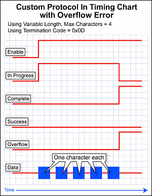
Turns ON if the CPU receives more Characters than specified in the Max Number of Characters before seeing the Termination Character(s) specified. The Overflow Error bit will turn OFF again when new data is received. |
|
Use Structure |
Checkbox |
Optional |
Enables the use of Structures. |
Note: One of theSerial Ports must be configured for ASCII/Custom Protocol before configuring this instruction.
Note: Tag Values are updated immediately as each Ladder Rung is executed, top to bottom. However, Tag Values representing physical Outputs are only applied to the physical Output after the END statement of the last Task to be scanned is reached. Outputs in Remote Base Groups have additional limitations regarding Update Intervals.
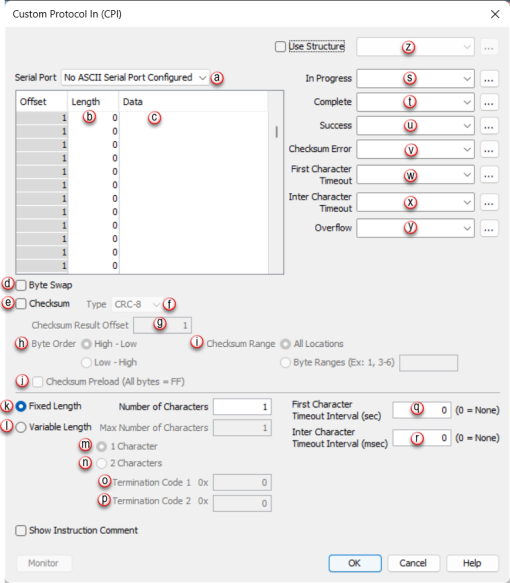
When Custom Protocol In Instruction is selected the window shown below opens.