|
|
Topic: P139 |
Modbus Write (MWX) Instruction |
|
|
|
Topic: P139 |
Modbus Write (MWX) Instruction |
|
Icon / Button = ![]()
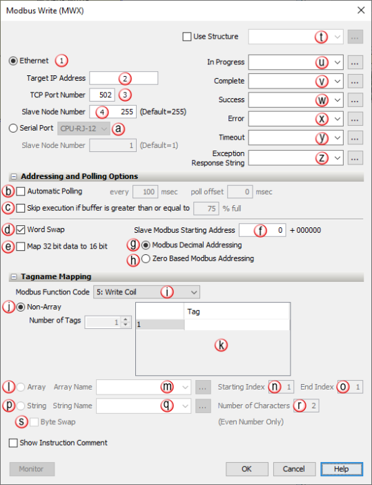
Perform Write requests from the CPU to Modbus TCP Ethernet and Modbus RTU Serial Slave devices.
|
Parameter |
Parameter Type |
Requirements |
Description |
|
Enable |
Ladder Input |
Must Have |
Edge-driven. If Automatic Polling is selected, the instruction becomes Level-driven. When Enable is ON, the instruction will operate every scan. When Enable is OFF, the instruction is not solved, and its outputs are not updated. |
|
Ethernet Port |
Selectable Option with Drop-down Selection |
Must Select Ethernet Port or Serial Port |
CPU External Ethernet Port that will send Modbus Write requests. |
|
IP Address |
Constant |
Must Have when Ethernet Port Selected |
IP Address of the Modbus TCP server that the Request will be sent to. Enabled when Ethernet Port is selected. |
|
TCP Port Number |
Constant |
Must Have when Ethernet Port Selected |
Default is 502 (number specified by Modbus TCP specification). Some devices will require a different value. Enabled when Ethernet Port is selected. |
|
Slave Node Number (Ethernet) |
Constant |
Must Have when Ethernet Port Selected |
Typically used for Modbus TCP to Modbus RTU bridges but some server devices may require different values. Applicable field is Enabled when Ethernet Port or Serial Port is selected. Ethernet Slave Node range is 0 to 255, with a default ofstrong> 255. |
|
Serial Port |
Selectable Option with Drop-down Selection |
Must Select Ethernet Port or Serial Port |
RS232 or RS485 CPU Port or P3-RS/RX Remote Slave Port that will Send Modbus Write Requests. |
|
Slave Node Number (Serial) |
Constant |
Must Have when Serial Port Selected |
Number assigned to the Slave device. Slave Node range is 0 to 247, with a default of 1. |
|
Use Structure |
Checkbox |
Optional |
Enables the use of Structure. |
|
In Progress |
Boolean Tag |
Optional |
Status Bit that specifies a Write Request is in progress inside of the CPU (sent from the instruction but not yet sent out the Ethernet Port). The Status Bit reflects the Status of the individual Write Request. |
|
Complete |
Boolean Tag |
Optional |
Status Bit that specifies a Write Request has been sent and a reply has been received, but it may not necessarily have been a good reply. The Status Bit reflects the Status of the individual Write Request. |
|
Success |
Boolean Tag |
Optional |
Status Bit that specifies a Write Request has been sent and a good reply has been received. The Status Bit reflects the Status of the individual Write Request. |
|
Error |
Boolean Tag |
Optional |
Status Bit that specifies a Write Request has been sent and a reply with an Error has been received from the Slave device within the specified Timeout period. Check the Exception Response String to see if it's an Error returned from the Slave device or check the Error Logs to see if it is an Internal Error. The Status Bit reflects the Status of the individual Write Request. |
|
Timeout |
Boolean Tag |
Optional |
Status Bit that specifies a Write Request has been sent but no reply was received within the specified Timeout value time. Timeout value is set up in the External Ethernet Port and RS232/RS485 Serial Ports of the Hardware Configuration. The Status Bit reflects the Status of the individual Write Request. |
|
Exception Response String |
String |
Optional |
String that holds the exception response Error. View the Communication Error Codes section of the help file for detailed information on Error Codes and possible corrective actions. |
|
|
|||
|
Parameter |
Parameter Type |
Requirements |
Description |
|
Automatic Polling |
Checkbox |
Optional |
The CPU will send out a request at the specified Poll Rate + Offset Time Value (msec). |
|
Skip Execution if Buffer is Greater Than |
Checkbox |
Optional |
Used with Automatic Polling, allows the user to back-off an instruction if the buffer is getting too full (for CPU ports only). Set by a percentage. See more details in the Communications topic. |
|
Word Swap |
Checkbox |
Optional |
For 32-bit tags, the Lower and Upper words are Swapped when data is Sent. |
|
Map 32 bit data to 16 bit |
Checkbox |
Optional |
Option allows the user to Map the Low Wordof 32-Bit Integer Tags in the CPU to 16-Bit Modbus addresses in the Slave device. |
|
Slave Modbus Starting Address |
Constant |
Must Have |
Modbus Starting Address of the Slave. |
|
Modbus Decimal Addressing |
Selectable Option |
Must Select Decimal or Zero Based Addressing |
Slave Modbus Starting Address field requires the standard Modicon style Addressing format range from 1 to 65536. |
|
Zero Based Modbus Addressing |
Selectable Option |
Must Select Decimal or Zero Based Addressing |
Slave Modbus Starting Address field requires the Standard Modicon style Addressing format range from 0 to 65535. |
|
Modbus Function Code |
Drop-down Selection |
Must have |
Selects functions the instruction will Write; Write Coils, Write Holding Registers or: 5: Write Coil 6: Write Single Register 15: Force Multiple Coils 16: Write Multiple Registers |
|
(Tagname Mapping) Non- Array |
Selectable Option |
Must Select Array or Non-Array |
Allows the user to specify the data from non sequential Tags that can be Sent in the Modbus Request. The number of Tags entered will determine the size of the> Request. |
|
Tag |
Numerical Tag / Boolean Tag |
Must Have when Non-Array Selected |
Specific Data Tags to be Sent. Note: For Modbus function code 16, if Non-Array mapping is selected, the max. number of tags is limited to 60, however, if the Map 32-bit data to 16-bit box is checked, the max. number of tags is increased 120. |
|
(Tagname Mapping) Array |
Selectable Option |
Must Select Array or Non-Array. Only used when "Force Multiple Coils" or "Write Multiple Registers" is Selected |
Allows the user to select the starting Tag and sequential number of Tags that will be Sent the data From or Written in the Modbus Request. The Sequential Mapping is based upon the System ID number. |
|
Array Name |
Numerical Tag |
Must Have when Array is Selected |
Specific Tag number to be Sent from. |
|
Start Index |
Constant |
Must Have when Array is Selected |
Starting position of the specific Array. |
|
End Index |
Constant |
Must Have when Array is Selected |
Ending position of the specific Array:
|
|
String Name |
String Tag/Constant |
Must Have when String is Selected |
Specifies the Tag that contains the ASCII string. |
|
Number of Characters |
Constant |
Must Have when String is Selected |
Enter even number of characters, max 128. |
|
Byte Swap |
Checkbox |
Optional |
Every Two Characters will be Swapped when data is Sent. |
Note: Communications using this instruction are performed through the External Ethernet Port on the CPU (upper (P3) or forward (P2) Ethernet Port), the RS232 Port on the CPU (RJ12 Port), the RS485 Port on the CPU (3-pin Terminal Block). Uses Modbus based protocol exclusive to the P1-Series CPUs.
Note:The Modbus Write instruction can be used withthe GS-EDRV100 (GS1, 2, 3) or the Modbus TCP communication option module (GS4, 20) if connected to the External Ethernet Port. See more details in the Communications topic.
Note: Tag Values are updated immediately as each Ladder Rung is executed, top to bottom. However, Tag Values representing physical Outputs are only applied to the physical Output after the END statement of the last Task to be scanned is reached. Outputs in Remote Base Groups have additional limitations regarding Update Intervals.
Note: During a runtime transfer, any Modbus communications instruction timeout bit will occur during transfer and resume once complete.
When Modbus Write Instruction is selected the window shown below opens.
To determine the total number of Modbus messages that can be sent per second (Ethernet throughput), use the following calculation:
Number of Modbus Masters/Slaves = 8
'Peak Scan Interval' System Tag = 10 msec.
8 x 10 msec. (100 scans)= 800 messages per second
Note: The number and size of the tags used in a specific Modbus message will increase the scan time, thus affecting the overall throughput.
Note: Another side effect of the queuing mechanism is that the instruction status bits may not be seen in the ladder. When an instruction has completed (Success, Exception Response, or Timeout), the CPU firmware will set the appropriate status bits. At the point that the CPU firmware pulls another message off the queue, it will reset the status bits of that instruction. The timing can work out in such a way that the status bits get set but the CPU firmware pulls off the instruction that contains those same status bits and resets them to start another iteration before the ladder code examines those bits.
Two things can be done to ensure reliable detection of status bits:
1. Do not use Automatic Poll and use interlocking logic to detect status completion of an instruction before enabling that instruction again. This is the most reliable method.
2. Ensure that the Automatic Poll time is long enough to prevent queueing of that same instruction.
See Communications Modbus Functionality help topic for more details.
In the following example, the CPU Ethernet Port is performing a Modbus TCP Write to four consecutive control coils in a Modbus TCP Slave device.