|
|
Topic: P196 |
Communications Capabilities |
|
|
|
Topic: P196 |
Communications Capabilities |
|
The AutomationDirect P-Series CPUs are provided with several Communications Ports, seven communications ports on the P3-550 and five communications ports on the P3-530. The Connectivity for each of these ports is described in the sections below. The Communication Ports available are:
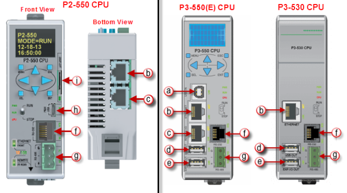
This port requires a USB Type A-B cable (such as the P3-EX-CBL6 cable).

The USB Port is the simplest method of connecting the Productivity Suite programming software to the P3-550 CPU. After the programming software has been installed, connect a USB A to B cable from the PC to the CPU. Once the software has been opened, click on CPU and select the “Choose CPU” option. The dialog shown below will appear.
Highlight theCPU listed in the dialog box and click on “Connect”. No configuration is required.
Note: The USB IN port is NOT compatible with older 1.0/1.1 full speed USB devices.
General Information:
Crossover cables can be used to directly connect two endpoint Ethernet devices such as a PC network interface card and the CPU. Patch (or Straight-through) cables are used to connect an endpoint Ethernet device to an Ethernet switch.
The External Ethernet Port can be used as a programming port, a Modbus TCP Client port, a Modbus TCP Server port, or to communicate with other P-Series CPUs. The External Ethernet Port can also be used to send emails using the EMAIL instruction.
Create a Connection:
To communicate with the Productivity Suite programming software, connect a crossover Ethernet cable from the PC to the CPU External Ethernet Port or connect a patch (straight-through) Ethernet cable from the PC to an Ethernet switch and another patch cable from the Ethernet switch to the External Ethernet Port. Once the software has been opened, click on CPU and select the “Choose CPU” option. The dialog shown below will appear.
Highlight the CPU that you wish to connect to and press the “Connect” button. You may see CPUs that are not on the same subnet as your PC within the CPU Connections dialog box, but this does not mean you can connect to them. To connect to the CPU, you must configure either your PC or your CPU to be in the same subnet. You can easily change the Ethernet settings of the CPU by highlighting it and selecting the "Change CPU IP/Name" button which will open the dialog shown below. Or if you prefer, the PC Setup section contains information on configuring the Ethernet settings of your PC.
Remote I/O Ethernet Port: Ethernet ports on P1, P2, and P3 remote modules, GS Drive communications modules and GS-EDRV100 are auto-MDI/MDIX so either straight-thru or crossover cables may be used.
Crossover cables can be used to directly connect endpoint Ethernet devices and the CPU. For example, connecting a P3-RS or P3-RX Remote Slave Module to the P3-550 CPU. Patch (or Straight-through) cables are used to connect an endpoint Ethernet device to an Ethernet switch.
The maximum distance for one cable or segment is 100 meters (328 feet). If the distance required between 2 devices is greater than 100 meters, add an Ethernet switch to extend the distance. An Ethernet switch can be added every 100 meters (or less) almost indefinitely. Each Ethernet switch added will incur some latency (actual amount differs between switches and manufacturers). So if a very long distance is needed between 2Ethernet devices, it may be better to convert to fiber optics.
The Remote I/O Ethernet Port is used to communicate to the Remote I/O Network, consisting of Remote Slave bases (P3-RS/RX modules) and GS Drives with a GS-EDRV100 Ethernet (GS1,2,3) or Modbus TCP (GS4) module. It is highly recommended that the network attached to this port be isolated from other networks and it is absolutely necessary that it be isolated from other Remote I/O networks. See Remote I/O and GS Drives topic for details.
Note:USB Project Transfers are NOT supported by the P3-530 CPU.
This Port serves two purposes: Data logging with the P3-530 or data logging and project transfers with the P3-550, both require a USB-Flash Removable Storage Device (may work with other pen drives).
Note: The USB OUT port is NOT compatible with older 1.0/1.1 full speed USB devices.
Note: P Series CPUs ONLY support up to a 32GB FAT formatted USB pen drive (P3 Series) or MicroSD card (P2 Series).
Data logging is set up in the Productivity Suite Programming Software Data Logger configuration window. See the Data Logger help file topic for setup instructions.
Project Transfer(P3-550 only) to and from a USB drive can be accomplished several different ways:
- Transfer project to USB Drive from PC programming software.
- Transfer project from USB Drive to PC programming software.
- Transfer project from USB Drive to P3-550 CPU.
- Transfer project from P3-550 CPU to USB Drive.
Note: You must first select the “Enable project transfer to/from USB drive” checkbox in the P3-550 CPU Module Configuration.
Note: Before transferring a project to the CPU via USB pen drive, ensure that you are NOT connected with the programming software either by USB or Ethernet. If you attempt the transfer with the software connected via USB or Ethernet, a CPUCON Error will occur and an message will appear on the LCD of the P3-550.
To transfer a project to or from a USB Drive from the PC programming software, insert the USB Drive into a USB Port on the PC. Go to File and TransferProject and select To USB Drive or From USB Drive.
To transfer a project to or from a USB Drive on the P3-550 CPU, press Menu on the CPU display LCD and scroll down to the M8USB DRV option.
Select “>SAVE->PEN” to load the project that is currently on the CPU down to the connected USB Drive.
Select “>LOAD->CPU” to load the project that is currently on the USB Drive to the CPU.
Caution: The
Expansion I/O Port
is ONLY for
connecting to other
Productivity Suite I/O
bases with a
P3-EX module in
the CPU slot. This
port is not a standard
USB A port. Note
that in the diagram above, pin
1 is used for the
System Reset
signal and is not the typical
+5VDC VBUS signal
on most
USB A ports.
DO NOT USE EXTENDERS, CONVERTERS OR HUBS OF ANY SORT ON THIS
PORT. A
P3-EX-CBL6 cable
ships with each
P3-EX Module. It
is not recommended to use any cable other than the one supplied.

After this connection is made, power cycle the system and the CPU will automatically detect the expansion I/O units. They can be used once the Hardware Configuration has been read into the programming software. Up to 4 expansion I/O bases may be added to a CPU.
The RS-232 Port can be connected to Modbus RTU master or slave devices, as well as devices that output non-sequenced ASCII strings or characters. The manner in which these devices are wired to the CPU depends whether the device is considered to be DTE (Data Terminal Equipment) or DCE (Data Communications Equipment).
If two DTE devices are connected together, the RX and TX signals should cross or the RX of one device should go to the TX of the other device and the TX of one device should go to the RX of the other device (as shown below).
The CPU is considered a DTE device. Most Modbus or ASCII devices being connected to the CPU will also be considered a DTE device and will need to swap TX and RX, but you should always consult the documentation of that device to verify. If a communication device, such as a Modem, is placed between the CPU and another Modbus or ASCII device it will most likely require connecting the signals straight across (TX to TX and RX to RX). Again, this can differ from manufacturer to manufacturer so always consult the documentation before wiring the devices together.
The RTS signal on pin 5 of the RS-232 Port will turn on when the TX signal is turned on and the RTS signal will turn off when the TX signal turns off. The amount of time that the RTS signal turns on before the TX signal turns on and the amount of time that the RTS signal waits before turning off after the TX signal turns off is adjustable in the P3-550 CPU Module Configuration or P3-530 CPU Module Configuration for the RS-232 Port. The RTS signal is very often required for media converters, such as a RS-232 to RS-422/485 converter (much like the FA-ISOCON). The RTS signal is sometimes required for use with Radio modems as well (Key on and off control).
There is also +5VDC @ 210mA on pin 2 available for powering an external device such as the C-more Micro panel.
The RS-485 Port is useful for connecting multiple Modbus and ASCII devices on one network and/or connecting devices to the CPU at distances greater than 50 feet (RS-232 limit). The RS-485 standard supports distances of up to 1000 meters without requiring a repeater. The RS-485 Port on the CPU can support up to 50 devices, depending on each device’s load (this assumes a 19K Ohm load for each device). This number can be increased by placing an RS-485 repeater on the network, if necessary.
This port only supports RS-485 2-wire connections. For 4-wire RS-485 or RS-422, a converter, such as an FA-ISOCON, should be used with the RS-232 Port.
A 120 Ohm resistor is required at each end of the network for termination.
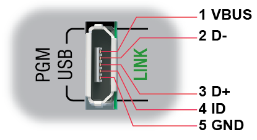
This port requires a Micro USB Type B cable (such as the USB-CBL-AMICB16 cable).
Create a Connection:
To communicate with the Productivity Suite programming software, connect a Micro USB Type B cable from the PC USB Port to Micro USB port on the P2-550 CPU. Once the software has been opened, click on CPU and select the “Choose CPU” option. The dialog shown below will appear.
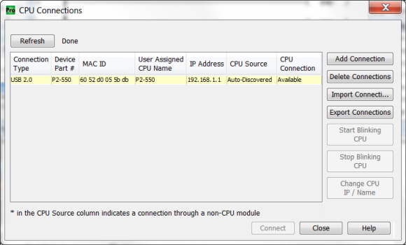
Highlight the CPU that you wish to connect to and press the “Connect” button. You may see other CPUs that are connected to your PC within the CPU Connections dialog box, but this does not mean you can connect to them.
Data logging is set up in the Productivity Suite Programming SoftwareData Logger configuration window. See the Data Logger help file topic for setup instructions.
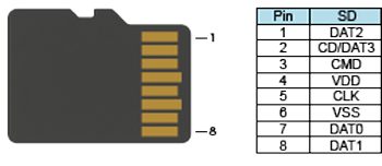
Note: microSD card is NOT included with the unit.
Note: P Series CPUs ONLY support up to a 32GB FAT formatted USB pen drive (P3 Series) or microSD card (P2 Series).