|
|
Topic:P400 |
P2-622 CPU Module Configuration |
|
|
|
Topic:P400 |
P2-622 CPU Module Configuration |
|
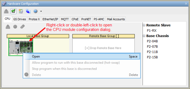
The P2-622 CPU is configured using the setup tools found in the Hardware Configuration window. First select the Local Base Group from the Hardware Configuration window by double left-clicking the Local Base Group or by right-clicking the Local Base Group and selecting Open from the drop down menu as seen below.
Note: When using the P2-622 with Productivity Suite v4.2.x.x or newer, a mandatory CPU firmware upgrade is required.
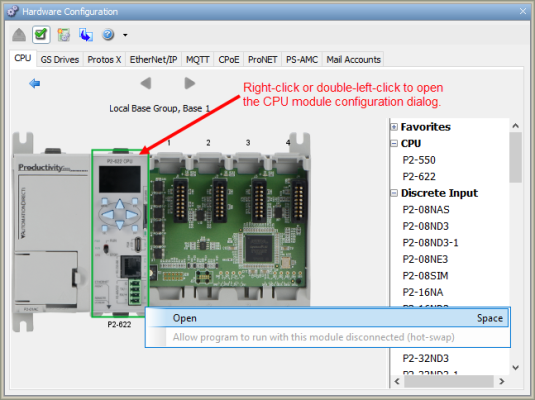
Then select the P2-622 by double-clicking the CPU or by right-clicking the CPU and selecting Open from the drop-down list. This will display the P2-622 configuration window.
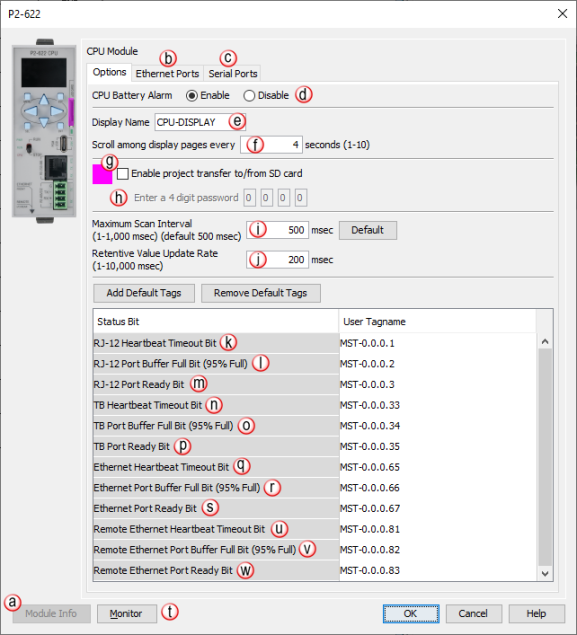
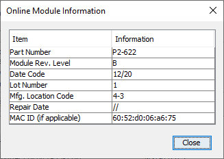
a. Module Info: Click on this button to open a window that displays information about the specific Module. A sample of the Online Module Information is shown below.
b. Ethernet Ports Tab: Click on this tab to go to the Ethernet Ports Configuration dialog.
c. Serial Ports Tab: Click on this tab to go to the Serial Ports Configuration dialog.
d. CPU Battery Alarm (Enable/Disable): Enables or Disables the Low Battery Voltage Alarm.
e. Display Name: Allows the entry of a unique Name for the CPU front panel OLED display, which can be selected in the LCD Display Page instruction.
f. Scroll among display pages every: Allows the entry of a value in Seconds from 1 to 10 to determine the Scroll Rate when using multiple Pages on the OLED display.
g. Enable Project Transfer To/From SD Card: Provides the option to Enable Project Transfer to a microSD or From a microSD card.
Note: Before transferring a project to the CPU via USB microSD Card, ensure that you are NOT connected with the programming software either by USB or Ethernet. If you attempt the transfer with the software connected via USB or Ethernet, a CPU CON error will occur and an error message will appear on the OLED of the P2-622.
Note: P2 Series CPUs support up to a 32GB formatted microSD card.
h. Enter a Four Digit Password: Allows the entry of a Password to protect the Project Transfer To/From the USB Drive microSD card.
i. Maximum Scan Interval: Sets the value for a Watchdog Timer that will trigger a Maximum Scan Interval tag if the Preset Time is exceeded.
j. Retentive Value Update Rate: User defined Tags that are set as Retentive will be Saved at the Periodic Rate specified here.
k. RJ-12 Heartbeat Timeout Bit: Allows the ladder logic in the CPU to know if a device has stopped communicating to the CPU. The RJ-12 Heartbeat Timeout Bit will become true if the RJ-12 Comm Heartbeat Value of the Serial Ports configuration is exceeded. The CPU will start a timer between each communication packet coming into the CPU. If a communication packet fails to be received by the CPU within the specified time period, this bit will be enabled. This bit only applies when the CPU ports are being used as a slave device and only monitors the time between the communications from the master device.
l. RJ-12 Port Buffer Full Bit (95% Full): A Boolean Tag can be assigned to this field and then used in the ladder code to indicate when communications are almost maxed out on this Port. When the Port becomes 95% full, the Bit becomes true (value of 1).
m. RJ-12 Port Ready Bit: Indicates when the RJ-12 Port is ready to be used for communications to other devices. RJ-12 Port Ready Bit will become momentarily False during a stop mode transfer of the programing software.
n. TB Heartbeat Timeout Bit: Allows the ladder logic in the CPU to know if a device has stopped communicating to the CPU. The TB Heartbeat Timeout Bit will become True if the TB Comm Heartbeat Value of the Serial Ports configuration is exceeded,.but only when the CPU ports are being used as a slave device The CPU monitors the time between the communications from the master device and enables the Bit if a communication packet fails to be received by the CPU within the specified time.
o. TB Port Buffer Full Bit (95%): A Boolean Tag can be assigned to this field and then used in the ladder code to indicate when communications are almost maxed out on this Port. When the Port becomes 95% full, the Bit becomes True (value of 1).
p. TB Port Ready Bit: Indicates when the TB Port is ready to be used for communications to other devices. TB Port Ready Bit will become momentarily false during a stop mode transfer of the programing software.
q. Ethernet Heartbeat Timeout Bit: Becomes True if the Ethernet Comm Heartbeat Value of the Ethernet Ports configuration is exceeded, but only when the CPU ports are being used as a slave device. The CPU monitors the time between the communications from the master device and enables the Bit if a communication packet fails to be received by the CPU within the specified time.
r. Ethernet Port Buffer Full Bit (95% Full): Becomes True if the External Ethernet Port Buffer is 95% full. A Boolean Tag can be assigned to this field and used in the ladder code to indicate when communications are almost maxed out on this Port. Instructions which use the Port Buffer Output Queues: MRX/MWX, RX/WX, GSR/GSW, AOUT, CPO
Note: MST bits correlating to any Buffer Full Bit (95% Full) correspond to the queue of instruction data that was executed but is still waiting to be transmitted out of a port. Each Serial port can buffer 100 instructions, and the local Ethernet port can buffer 1000 instructions. The 95% Bit is not related to the number of bytes waiting, but instead to the number of instructions that have data waiting.
s. Ethernet Port Ready Bit: Indicates when the Ethernet Port is ready to be used for communications to other devices. Ethernet Port Ready Bit will become momentarily False during a stop mode transfer of the programing software .
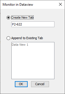
t. Monitor: Displays the window shown below with options for adding tags to Data View.
u. Remote Ethernet Heartbeat Timeout Bit: Only active if the Remote Ethernet Port is configured as User Defined. The bit becomes True if the Comm Heartbeat Value of the Remote Ethernet Port configuration is exceeded, but only when the CPU ports are being used as a slave device. The CPU monitors the time between the communications from the master device and enables the Bit if a communication packet fails to be received by the CPU within the specified time.
v. Remote Ethernet Port Buffer Full Bit (95% Full): Only active if the Remote Ethernet Port is configured as User Defined. The bit becomes True if the Remote Ethernet Port Buffer is 95% full. A Boolean Tag can be assigned to this field and used in the ladder code to indicate when communications are almost maxed out on this Port. Instructions which use the Port Buffer Output Queues: MRX/MWX, RX/WX, GSR/GSW, AOUT, CPO
Note: MST bits correlating to any Buffer Full Bit (95% Full) correspond to the queue of instruction data that was executed but is still waiting to be transmitted out of a port. Each Serial port can buffer 100 instructions, and the local Ethernet port can buffer 1000 instructions. The 95% Bit is not related to the number of bytes waiting, but instead to the number of instructions that have data waiting.
w. Remote Ethernet Port Ready Bit: Indicates when the Remote Ethernet Port is ready to be used for communications to other devices. Remote Ethernet Port Ready Bit will become momentarily False during a stop mode transfer of the programing software.
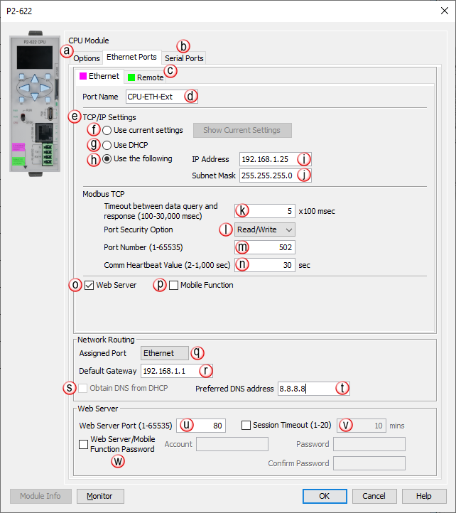
a. Options Tab: Click on this Tab to go to the Options dialog.
b. Serial Ports Tab: Click on this Tab to go to the Serial Ports Configuration dialog.
c. Remote Tab: Click on this Tab to go to the Remote Ethernet Port Configuration dialog.
d. Port Name: Allows the entry of a unique Name for the Ethernet Port. This Name is referenced in the Communications instructions (MRX, MWX, RX, WX).
e. TCP/IP Settings: The IP Setting of this Port may be changed in several ways:
The Settings may be entered manually in the Choose CPU tool. This allows the user to make changes to the IP to allow connection by the computer running the Productivity Programming Software. Changes are sent using Multicast Messages.
The Settings can be saved as part of the project. This must be Enabled in the P2-622 Hardware Configuration Settings by selecting Use the following (discussed on Items i, j, q, & r below). If handled this way, the Settings stored in the project will take effect at Project Transfer and at boot up only. The Settings may be changed after boot up.
f. Use Current Settings: When selected, Project Transfer or boot up will not make changes to the TCP/IP Settings of the CPU.
g. Use DHCP: Specifies that the CPU should request its IP Settings from a DHCP Server on the network.
Note 1: If the CPU is set to use DHCP for its IP Settings, it cannot in all likelihood be used as a Modbus TCP Server, since most industrial Modbus TCP Clients are targeting a fixed IP address. If the CPU is set to DHCP, its IP address may change on any given day and the Modbus TCP Client will not be able to target it.
Note 2: Selecting Show Current Settings and DHCP = No, indicates the CPU could not find an available DHCP server. A default link local address of 169.254.x.x will be assigned if no available server is found.
Note 3: Only after a power cycle will the CPU begin to search for an available DHCP server.
Note 4: Remote Ethernet Port must be on a different subnet from the External Ethernet Port. If the DHCP server assigns an IP that will create a subnet conflict, the DHCP assignment will be ignored and a non-critical error will be generated in the CPU.
h. Use The Following: If this Option is selected, the CPU will set itself to the specified project Settings upon Project Transfer or at boot up.
i. IP Address: This field is where the IP Address is specified in Four Octets.
For Example: 192.168.1.5
Note: Entering an IP Address reserved for specific functions will cause an error dialogue box to be displayed upon project compile.
IP address cannot begin with 127
The bits of the network or host portion of an IP address cannot be all 0's or all 1's. For example, 192.168.170.0 with network mask of 255.255.254.0 is invalid since the bits of the host portion of the address are all 0's.
IP address must between 1.0.0.1 and 223.255.255.254 (excluding 10.20.x.x, used for Local /Remote I/O network).
Note: The 10.20.x.x address range is reserved for Remote I/O supported by a Productivity CPU
j. Subnet Mask: Specified in Four Octets (i.e., 255.255.255.0 ) and used in conjunction with the IP Address to configure a Logical Network.
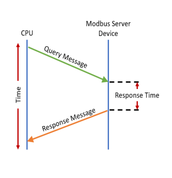
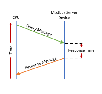
k. Timeout Between Data Query and Response: The Time period between the queries sent from the CPU (via a Communication instruction, such as a MRX, MWX, RX or WX, and GS Drives) and the Time a response from that device is received. If the Response takes longer to receive (or is not received) than the specified Time period, a Timeout Error will occur for the given instruction. Each instruction has a Timeout Status bit that can be assigned to it. See the diagram shown below.
Note: The Timeout value used applies to both MQTTS & Modbus TCP connections.
l. Port Security Option: Can be used as a simple Security measure to prevent Modbus TCP write requests from being accepted by the CPU. To allow Reads and Writes, select Read/Write.
m. Port Number: The listening TCP Port Number for Modbus TCP connections. If necessary, this value can be adjusted for advanced router access. In most situations, this Number should be left at 502.
n. Comm Heartbeat Value: If a communication packet fails to be received by the CPU within the specified time-period, the Ethernet Heartbeat Timeout Bit will become true. If a value is placed in this field, the CPU will start a timer between each communication packet coming into the CPU. This feature allows the ladder logic in the CPU to know if a device has stopped communicating to the CPU.
o. Web Server: Allows a non-secure web connection via the Ethernet Port to the CPU to access the microSD card and view read-only system tags. When enabled, a port number selection is required.
p. Mobile Function: Enables Remote Access via the External Ethernet Port which allows the CPU Data Remote Monitor App to monitor the selected tags.
q. Assigned Port: The External Ethernet Port is the only port with routing capability.
r. Default Gateway: Typically the IP Address of the router on the network and specified in Four Octets (i.e., 192.168.1.1). The Default Gateway Address receives an outgoing message from the CPU that is sent to a target IP Address that is not in the Local Subnet.
s. A DNS (Domain Name Service) server contains a database of public IP addresses and their associated host names and translates those common names to IP addresses. For example, a DNS server translates “www.automationdirect.com” to the IP address 205.151.114.26.
Note: Other names for a DNS server include name server, name server, and domain name system server.
t. Preferred DNS address: the IP Address of the first DNS server to contact for resolving the name to an IP Address.
u. Web Server Port (1-65535): (Default 80) Allows user to set a port number ranging from 1-65535 for the web server.
v. Session Timeout (1-20): Allows the user to set a specific time limit (1-20 mins.) on inactivity that will close the WebServer connection. If there is no activity between the PC and the Web Server for the specified time limit, the connection will close.
w. Web Server/Mobile Function Password: Allows the user to set a password for Remote Access using the CPU Data App or access to the Web Server.
Enter an account name & password of up to a combination of 20 numbers and characters (can include special characters).
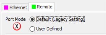
x. Port Mode: Determines whether the Remote Ethernet Port is configured as the Default (Legacy Setting) for native Remote I/O (such as remote slaves, GS Drives, Protos X groups, or AMC modules) or as User Defined.
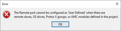
Note: Configuring the port as User Defined will disallow the configuration of remote slaves, GS Drives, Protos X groups, or AMC modules in the system. If there are remote slaves, GS Drives, Protos X groups, or AMC modules already in the system hardware configuration, the Remote Port cannot be configured as User Defined.
Remote Port Default (Legacy Setting) Configuration (settings 1 & 2 below only apply if the Remote Port is configured as the Default (Legacy Setting))
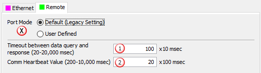
1. Timeout Between Data Query and Response: The Time period between the queries sent from the CPU (for Remote I/O Nodes and the Time a Response from that device is Received. If the Response takes longer to receive (or is not received) than the specified Time period, a Timeout Error will occur for the given device and an Error will be generated in the Error Log. For Remote Slave Timeouts, the Error will be critical or non-critical, dependent on the Hot-Swap settings for that unit and its I/O Modules (See diagram shown above).
2. Comm Heartbeat Value: Specifies how long the Remote I/O Slaves should wait for a communication packet from the CPU. If a communication packet is not received from the CPU within the specified time period, all outputs on the Remote Slave will be turned OFF.
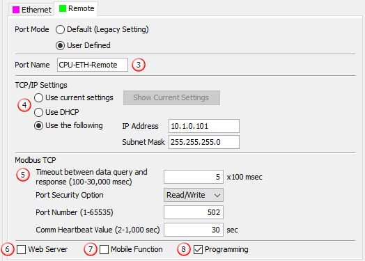
3. Port Name: Allows the entry of a unique Name for the Remote Ethernet Port. This Name is referenced in the Communications instructions (MRX, MWX, RX, WX).
4. TCP/IP Settings: The IP Setting of this Port may be changed in several ways:
The Settings may be entered manually in the Choose CPU tool. This allows the user to make changes to the IP to allow connection by the computer running the Productivity Programming Software. Changes are sent using Multicast Messages.
Note: Manual setting of the port IP Settings is only available if the port has already been configured for Programming (see item 8 below)
The Settings can be saved as part of the project. This must be Enabled in the P2-622 Hardware Configuration Settings by selecting Use the Following (discussed on Items f thru j above). If handled this way, the Settings stored in the project will take effect at Project Transfer and at boot up only. The Settings may be changed after boot up.
The Settings can be set using a DHCP server. Refer to item g above for details on using a DHCP server.
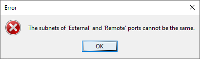
Note: The subnets of the Ethernet and Remote ports cannot be the same
5. Modbus TCP: Settings that apply to Modbus TCP communications that utilize the Remote Port. Refer to items k thru "n" above for details.
6. Web Server: Allows a non-secure web connection via the Remote Port to the CPU to access the microSD card and view read-only system tags. When enabled, a port number selection is required.
Port: (Default 80) Allows user to set a port number ranging from 1-65535.
7. Mobile Function: Enables Remote Access via the Remote Port which allows the CPU Data Remote Monitor App to monitor the selected tags.
8. Programming: Allows the Productivity Programming Software to discover, go Online, change CPU IP / Name, Transfer Projects, and perform firmware updates to the system.
There are two Configurable Serial Ports on the P2-622:
• One RJ-12 configurable RS-232 / RS-485 serial port, and
• One four-pin Terminal Block (TB) style configurable RS-232 / RS-485 serial port.
Both Ports are capable of Modbus RTU Client (device that initiates communications requests) and Server (device that responds to communications requests) communications. They are also capable of ASCII outgoing strings and incoming strings.
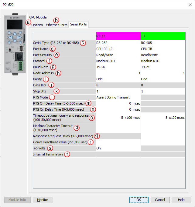
When the Serial Ports Tab is selected, the Serial Ports settings are displayed as shown below.
a. Options Tab: Click on this Tab to go to the Options dialog.
b. Serial Ports Tab: Click on this Tab to go to the Serial Ports Configuration dialog.
c. Serial Type (RS-232 or RS-485): Allows the Port to be configured as RS-232 or RS-485 from the drop-down list.
d. Port Name: Allows the entry of a unique Name for each Port. This name is referenced in the Communications instructions (MRX, MWX, RX, WX) and ASCII instructions (AIN, AOUT, CPO, CPI).
e. Port Security: Can be used as a simple Security measure to prevent Modbus RTU write requests from being accepted by the CPU. To allow Reads and Writes, select Read / Write.
f. Protocol: Determines whether the Port is used for Modbus RTU communications, sending or receiving ASCII Strings or performing the Custom Protocol function.
g. Baud Rate: Choose from a drop-down list of available Baud Rates (1200, 2400, 9600, 19200, 33600, 38400, 57600, and 115000). All devices communicating on the network must be set to the same Baud Rate.
h. Node Address: This field can be set from 1 to 247 and is used to uniquely identify the CPU on the network, only when the CPU is a Modbus RTU Server device. This setting is sometimes referred to as a Station Address.
i. Parity: Used for simple, low-level Error Detection. All devices on the network must be at the same Parity setting. Valid selections are None, Even, and Odd.
j. Data Bits: Determines whether the communications packet uses Seven Data Bits or Eight Data Bits. Eight Data Bits is the only valid selection for Modbus RTU. Either Seven or Eight Data Bits can be selected when using ASCII communications. Set this field to match the device that is connected to the CPU.
k. Stop Bits: Determines whether the communications packet uses One or Two Stop Bits. Set this field to match the device that is connected to the CPU.
l. RTS Mode (RS-232 only, RJ-12 only): Set the RTS mode to control the Request To Send signal out of the Serial port.
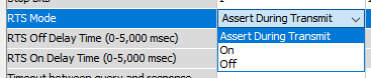
• Assert During Transmit: Make the RTS signal turn ON in the time between the RTS ON delay and RTS OFF delay.

• On: Make the RTS signal ON all the time.

• Off: Make the RTS signal OFF all the time.

m. RTS Off Delay Time (RS-232 Only): The amount of Time between the end of the data transmission and when the RTS signal is turned OFF. The diagram below illustrates this. This setting may be needed when using media converters (RS-232 to RS-422/485 converters) and/or radio modems. A delay may be needed at the end of the data transmission for processing time in the device.
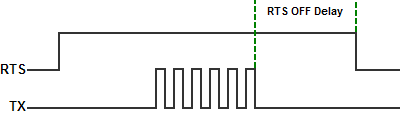
n. RTS On Delay Time (RS-232 Only): The amount of Time between when the RTS Signal is turned ON and the data transmission begins. The diagram below illustrates this. This setting may be needed when using media converters (RS-232 to RS-485 converters) and/or radio modems. A delay may be needed after the assertion of the RTS Signal and when the data transmission begins for processing time in the device.

o. Timeout Between Query and Response: The allowable Time between when a query is sent from the CPU (via a Communication instruction, such as an MRX, MWX, RX, or WX) and when a Response from that device is Received, before a Timeout Error will occur for the given instruction. Each instruction has a Timeout Status bit that can be assigned to it.
p. Modbus Character Timeout: The Time between two bytes (or characters) within a given Modbus Message. The Modbus RTU specification states that this time must be no more than 1.5 Character Times (real time based on Baud Rate). Sometimes delays occur between bytes when using radio modems, media converters, etc. This setting allows some tolerance in these situations for the incoming Modbus Messages in the CPU. The CPU will wait for the amount of time specified in this field before discarding the incomplete packet. If the CPU does not receive the remainder of the Message within the specified Time Frame, it will discard the first portion of the Message and wait for a new Message.

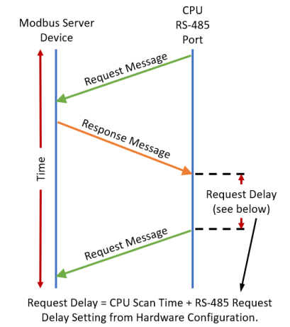
q. Response/Request Delay (RS-485 Only): Used when the CPU is a Modbus RTU Server or Client on the RS-485 Port. The total Response Time can be up to the Total CPU Scan Time + the Value specified in this field. When using 2-wire RS-485 communications, sometimes Echoes can occur since both devices use the same differential signal pair to send and receive.
• If acting as a Server, upon receiving a Modbus Request, the CPU will wait for the time period specified in this field before sending a Response. This can be used with slow clients that need extra time to change from sending to receiving.
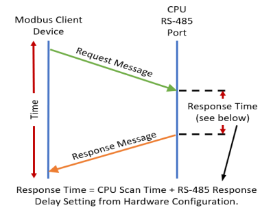
• If acting as a Client, after receiving a Modbus Response, the CPU will wait for the time period specified in this field before sending another Request. This can be used to delay request messages in order to give extra time for slow server devices.
r. Comm Heartbeat Value: If a value is placed in this field, the CPU will set the System Bit RJ-12 Heartbeat Timeout Bit or TB Heartbeat Timeout Bit to True, if a communication packet fails to be received by the CPU within the specified Time period. This feature allows the ladder logic in the CPU to know if a device has stopped communicating to the CPU
s. +5 Volts: This feature can be selected to be ON or OFF (default is ON) and only applies to the RJ-12 port (pin 2) and is intended for supplying +5 volts to power a C-more Micro panel. It should be disabled if not used as to not unintentionally cause damage when connecting to something other than a C-more Micro panel. This option is not available when the RJ-12 port is configured as RS-485.
t. Internal Termination: This feature can be selected to be ON or OFF (default is OFF) and only applies to the RJ-12 port when the port is configured for RS-485. It enables a 120 Ohm resistor to be used for the RS-485 network.