Analog Meter
-
Signed Int 16/32
-
Unsigned Int 16/32
-
BCD Int 16/32
-
Floating Point 32
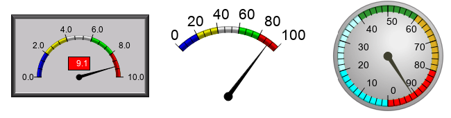
Use the Analog Meter Object to display tag name variable data in a conventional meter format. Data can represent levels, currents, flows, speeds, and more.
General Settings
Object Styles
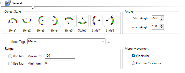
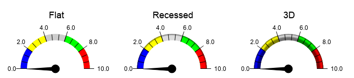
Choose from 8 preset styles. Meter styles set some of the values in the General tab.
Angle
Start Angle: the location of needle when the tag value is at the minimum range setting.
Sweep Angle: the number of degrees the needle moves from minimum to maximum range.
Range
Sets upper and lower value limits. You can configure maximum and minimum independently.
The maximum value must be greater than the minimum.

Use Tag
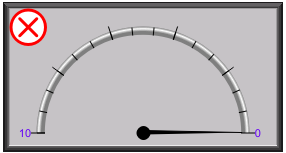
Tick the box beside Use Tag to set the range from a PLC or another object after you send the project to the panel. If the maximum tag value is less than the minimum tag value, a red X appears in the top left corner.
Static
If you do not apply Use Tag, the project determines static values and you cannot change them once you send them to the panel. To change the values, transfer a new project to the panel with your new settings.
Meter Movement
Clockwise
The needle moves clockwise from minimum to maximum range.
Counter-Clockwise
The needle moves counter-clockwise from minimum to maximum range.
Appearance
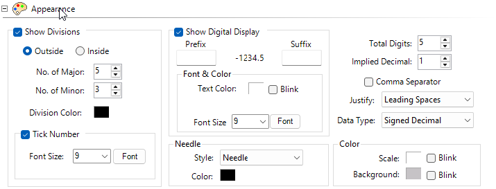
You can set font and color in most Appearance fields.
Show Divisions
Tick the box beside Show Divisions to tick marks on the meter. You can position them on the left, right, top, or bottom based on the slider style.
No. of Major
The number of large sections dividing the slider.
No. of Minor
The number of sections nested in the No. of Major dividing the slider with smaller marks.
Tick Number
Tick this box to show divisions as tick marks on the meter.
Show Digital Display
See a digital number that represents the slider location. It adjusts automatically based on font size selected, the prefix and suffix, and the value shown.
The Digital Display background color corresponds to the Alarm Band color range.
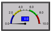
Needle
Select the style for the needle.
Prefix/Suffix
Enter text to display before or after the numeric value.

Digits
-
Total Digits: for a number with more digits than configured truncates the most significant digit.
-
Implied Decimal: determines the position of an implied decimal place with an integer data type tag.
-
Precision: determines the decimal placement in floating point values.
| Note: | Use Tag for Decimal Point setting overrides this setting. |
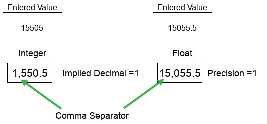
Comma Separator
Places a comma separator between hundreds and thousands.
 Example:
15000 or 15,000
Justify
-
Leading Zeros: displays a 0 instead of spaces for digits before the first non-zero digit.
-
Leading or trailing spaces: does not display any unused digits.
Data Type
Display the Unsigned Int 16/32 data type in Unsigned Decimal, Octal, or Hex format.
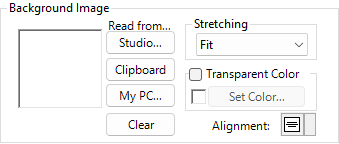
Background Image
Choose a background image for the meter.
Alarm Band
Enter different settings for low and high values. The Digital Display background changes based on these values.
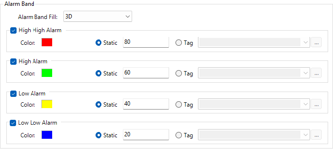
Alarm Band Fill
Select a color for each Alarm level.
Alarm Levels
-
High and High High: the meter scale is this color above alarm value.
-
Between Low and High: the meter scale is the default color.
-
Low and Low Low: the meter scale is this color below alarm value.
Font and Color
Behavior
For information on Press Delay and Release Delay, see Behavior.
CM051