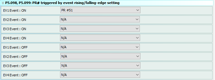
Use the event ON/OFF settings to configure PR mode triggers for the ON/OFF states of up to four events. PRs #51 through #63 are available, and can be configured through the PR Mode Setting menu. To view your ON/OFF events, use the Chart tab.

How to Use Events
An Event in SureServo2 is a way to automatically call a Path (example: make the motor move a certain distance) when a digital input turns ON or OFF. This is only for use in PR Mode. There are three things required to program this behavior:
1.) Define a Digital Input as an Event
2.) Define which Path to execute when the Event is triggered
3.) Program the Path
Refer to Chapter 7 of the SureServo2 User Manual for information on using Events for Registration (High Speed Capture and Compare).
Step 1
Define the Digital Input as an Event.
The Digital Inputs are configured in P2.010 through P2.017, and P2.036 through P2.040. Enter one of these values in a DI register to configure it as an Event input:
Step 2
Define which PATH to execute when the Event is triggered.
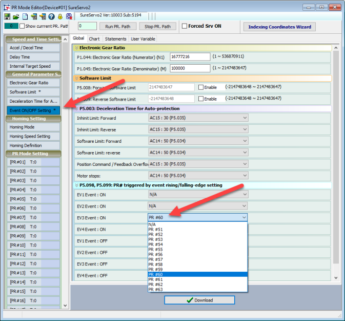
P5.098 and P5.099 define which Paths get called when an Event is triggered. P5.098 sets the Paths that gets called when an Event turns ON (rising edge). P5.099 sets the Path that gets called when an Event turns OFF (falling edge). The only Path that are available for the Event function are PR#51 – PR#63. Set these Paths using the drop down boxes in the PR# triggered by event rising/falling-edge setting window. You can also set these parameters through the Parameter Editor.
Step 3
Program the Path.
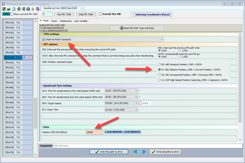
Once the Event is configured, all that remains is to define the commands in the chosen Path (PR#51 – PR#63).
Example:
Configure the servo to move 10,000 PUU every time a Digital Input turns ON. This example will use DI9, Event trigger #3, and PR#60.
1.) Ensure the drive is in PR Mode (P1.001 = 0x0001)
2.) Define Digital Input 9 as Event trigger #3 (P2.036 = 0x013B)
3.) Configure Event #3 to call PATH PR#60

4.) Program PATH PR#60 as a Point-to-Point Command, Relative Positioning, Position = 10,000 PUU.

Now, each time DI9 turns ON (when the servo is enabled), the motor will move 10,000 PUU.
 Note: If the Position Command Type is set to ABS, the motor will move to Position 10,000 when DI is first triggered. All subsequent DI triggers will not cause motion because the motor will already be at its commanded position.


