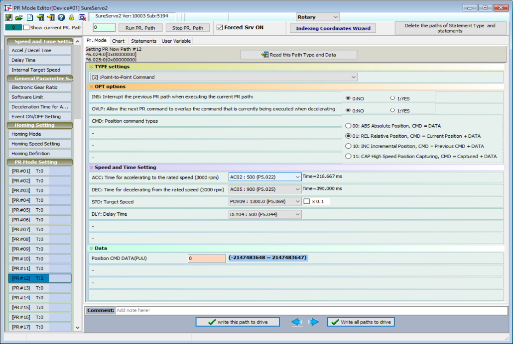
The PR Mode Setting group inside the PR Mode Editor window allows you to create constant speed moves, point to point moves, statements, jumps, writes, and gives you the ability to initiate indexing control. All these advanced commands (except statements) are stored in paths labeled PR#00 – PR#99. Each path consists of two 32-bit registers. The SureServo2 User Manual gives a detailed explanation of the path structures so you can manually edit the parameter values. However, it is highly recommended to use SureServo2 Pro to populate the paths (especially the configuration – see below). Statements are stored separately from the Parameters and can only be entered through SureServo2 Pro.
Each path corresponds to a pair of parameters:
| Path | Parameters |
|---|---|
| PR#00 | P6.000, P6.001 |
| PR#01 | P6.002, P6.003 |
| PR#02 | P6.004, P6.005 |
| ... | |
| ... | |
| PR#98 | P7.096, P7.097 |
| PR#99 | P7.098, P7.099 |
PR#00 is a special path reserved for Homing functions. Other than PR#00, all other paths can be used freely.
PR#51 through PR#63 can be used as normal paths. They are special in that they can be triggered by Events (digital inputs turning ON or OFF). See the Event ON/OFF tab in the PR Mode Editor window. Also see P5.098-P5.099 and P2.010-P2.017 for more details.
In general, the first Parameter of a path is the configuration (command type, options, etc.). Instead of storing Acceleration time, Deceleration time, Target Speed (for point-to-point moves), and Delay time values in the 32-bit path words, these values are stored in P5.020 – P5.075, and those storage parameters are pointed to by the path. If you need complete flexibility in your PLC application see the path configuration details in the UM under the description of P6.002. Otherwise, we recommend using SureServo2 Pro.
The second parameter is normally reserved for the Data (target position, target speed (for a speed move), etc.). This is especially convenient for external comms control: you can configure the type of move required via SureServo2 Pro (the software can decipher the bits and bytes for configuration), but an external controller (PLC) can easily change target speeds, target positions, etc., by writing to the 2nd Parameter.
| Setting | Purpose | Example |
|---|---|---|
| 1st Parameter | Configuration | P6.024 |
| 2nd Parameter | Data | P6.025 |
Configure path PR#12 for a RELative point-to-point position move 3333 PUU long, with an Acceleration time of P5.022, a Deceleration time of P5.025, a Target speed of P5.069, and a Delay time of P5.044. The resulting parameter values:
P6.024 = 4805186 (0x00495242)
P6.025 = 3333 (0x00000D05)
The value in P6.024 contains all the configuration for this move. P6.025 contains the target Position. To change the target move value from an HMI or PLC, the controller would only have to modify the value in P6.025.

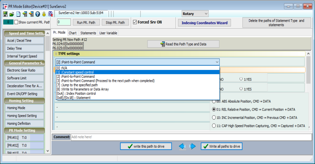
There are seven different actions available for the PR path Types. Each Type has different options that become available after a selection is made. The seven types are:
Type 1: Constant Speed Control
Type 2: Point-to-Point Command
Type 3: Point-to-Point Command (Proceed to the next path when completed)
Type 7: Jump to the specified path
Type 8: Write to Parameters or Data Array
Type A: Index Position Control
Type B/1B: Statement
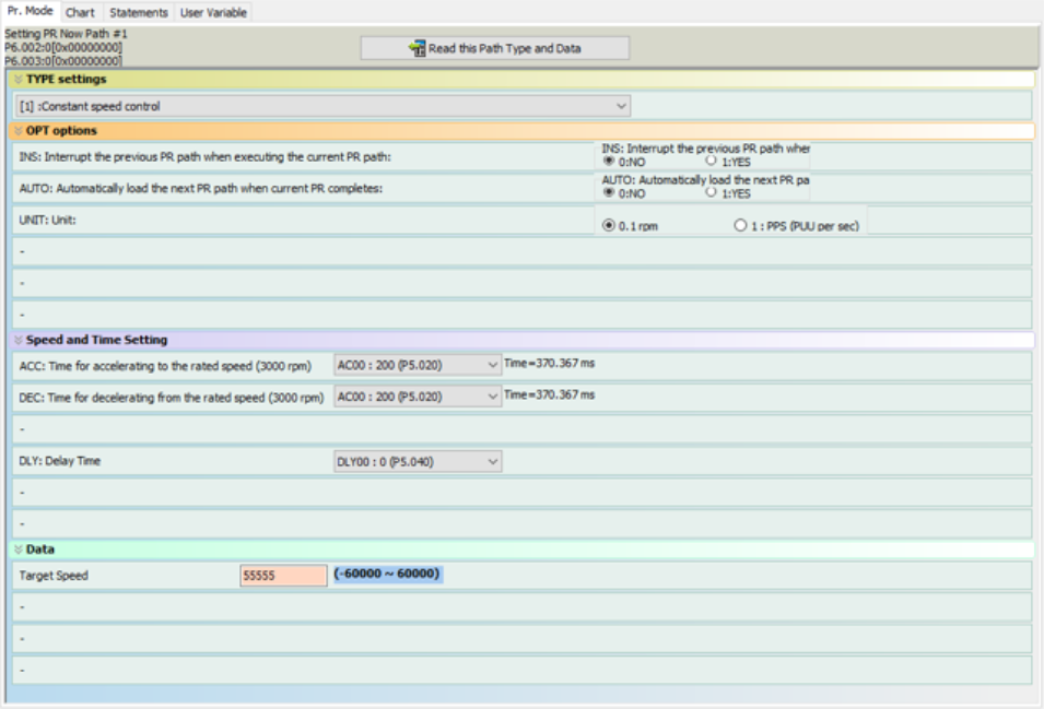
For motion commands, there are some special settings considerations when configuring a move.
| Option | Function |
|---|---|
| INS | Interrupt the previous PR path when executing the current PR path. |
| AUTO/OVLP | Allow the next PR path to automatically start In Constant Speed Control, the AUTO setting loads the next PR path when the motor reaches the Target Speed. In Position Moves, the OVLP setting causes the next PR path to start when the current move begins to decelerate. In Position Moves, the Delay Time should be set to 0. |
| Units | Defines the unit of measure for the value in the Data section (Target Speed or Target Position) . |
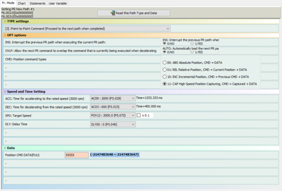
| CMD | Position Command Types (see Figure 7-17 in the SureServo2 User Manual for more detail). |
| ABS | The motor will move to the position specified in the Data section. |
| REL | The motor will move to (current motor position) + Data. If a previous move was in progress, the rest of the original move is discarded. |
| INC | The motor will add the Data to any existing move. If a previous move was in progress, the remaining original move’s distance is added to the new move distance. |
| CAP | The motor will perform a relative move (distance = Capture Position + Data) after the Capture function is engaged. As with the REL command above, the finishing point of the original move is discarded. |
| Delay Time | After a Constant Speed Move reaches Target Speed or a Position Move reaches Target Position, this Delay Time begins. After this time delay, the currently executing move is considered complete. |
Enter the desired configuration for speed or position based-moves. Notice that after configuring the ACC, DEC, and SPD settings, the actual time for acceleration and deceleration are calculated on the ACC and DEC row.
Type 2 and Type 3 Position moves are identical, except the “(Proceed to next path when completed)” selection will automatically execute the next PR path after the current move is finished.
See Figure 7-15 and Figure 7-17 in the SureServo2 User Manual for more details.
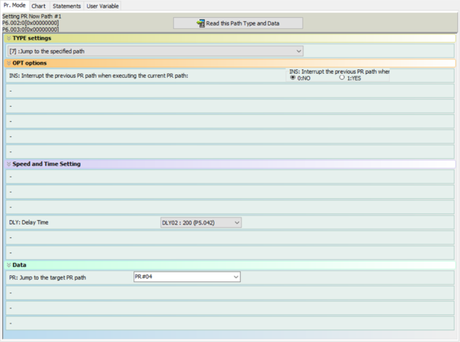
When this command is executed, the drive delays for the time specified in Delay Time (in ms), then automatically executes the path specified in Data.
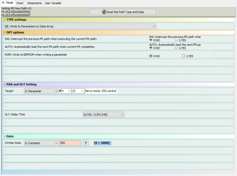
Use this Type to write to Parameters or the Data Array. The source of the Data can be a constant value or can be from Parameters, the Data Array, or Monitor Variable values.
See the section entitled “Write Command” in Chapter 7 of the SureServo2 User Manual for more details.
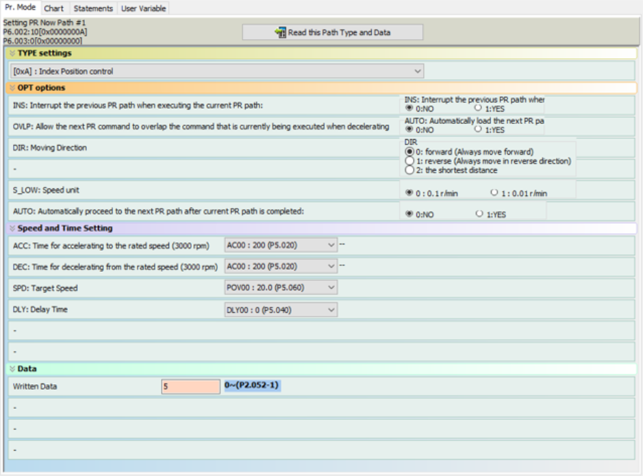
Use this Type to move according to the Index Coordinates entered in the “Indexing Coordinates Wizard”. The drive must not be Enabled, to fully set up the Index Coordinate Wizard.
See the section entitled “Index Position Command” in Chapter 7 of the SureServo2 User Manual for more details.
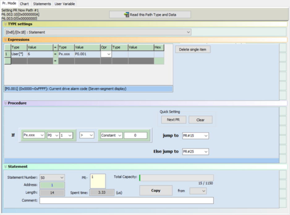
Use this Type to enter Expressions and Statements. Note that Statements can only be entered through SureServo2 Pro software. You cannot enter statements by configuring the bits and bytes of P6.02 – P7.99.
See the section entitled “Statement (Arithmetic Operations)” in Chapter 7 of the User Manual for more details.
