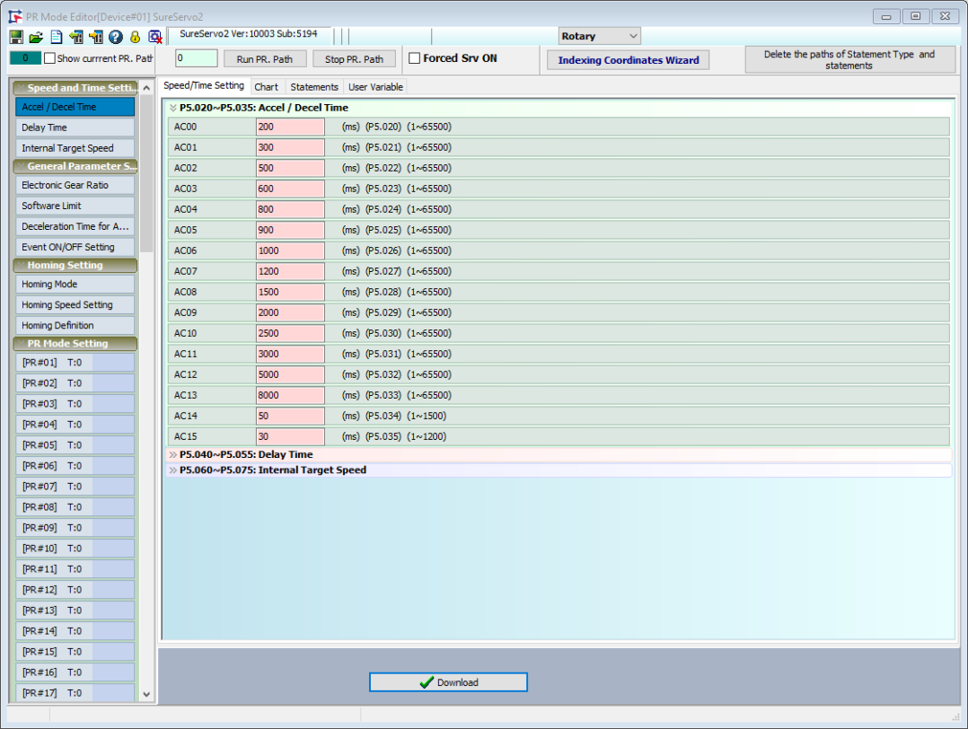
Position Register (PR) Mode is a built-in motion control mode that allows the servo drive to change the motion command at any time. SureServo2 has 99 independently configurable "Paths" that can be defined as Point-to-Point Moves, Speed Commands, Jumps, Index Control, Writes, or simple logic evaluation.
In a traditional control method, the motor runs when a digital input (DI) triggers one PR. The command is non-continous and can be interrupted but not changed. For SureServo2, the command can be interrupted or changed by an external trigger. This allows for functions such as homing control, position control, speed control, procedure jump, parameters written-in, etc.
9 main homing modes and more than 30 sub-item combinations are included.
Allows for constant speed control in speed mode, including acceleration/deceleration curve programs.
Allows position command types such as absolute command, relative command, incremental command, CAP command, etc.
Jump function can change the sequence of procedure.

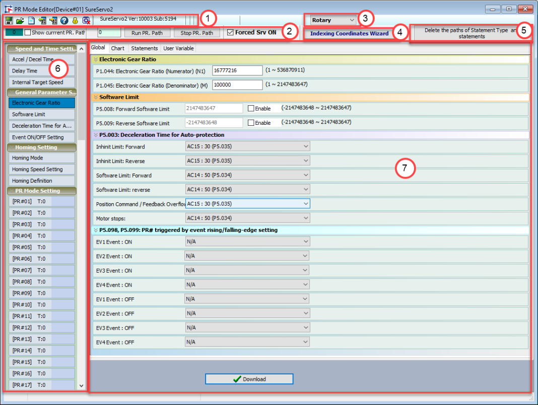
The PR Mode Setup screen can be broken down into seven functional areas:
1.) The toolbar - this contains functions such as saving and loading the PR file. See PR Mode Toolbar for details.
2.) PR Simulation - use this to command PR paths to execute and to monitor which paths are currently executing. See PR Mode Simulation for details.
3.) Rotary/Linear Selector - use this to change between Rotary and Linear mode. Changes the units for ACC and DEC.
4.) Indexing Coordinates Wizard - use this button to configure indexing coordinates or create an indexing table. See Using the Indexing Coordinates Wizard for details.
5.) Delete the paths of Statement Type and statements - removes statement paths and saved statements from the configuration. A confirmation window will appear when clicked.
6.) Mode setting - contains all the different modes that can be set for editing. See Setting the Mode for details.
7.) Main setting window - contains all the options that can be configured for the selected PR path. See Using the Main Settings Window for details.
The toolbar at the top of the PR Mode Setting screen contains the following buttons:
| Button | Function |
|---|---|

|
Open Files
Open a previously saved parameter file (*.par) to configure the PR mode. |

|
Save as Files
Save the PR mode as a parameter file (*.par). |

|
Open New Edit
Restart configuration. Clicking this button will reset all settings in the Main Setting Window to 0. You will be prompted to confirm this choice - all unsaved changes will be lost. |

|
Write All to Servo
Copy edited PR Mode related parameters from the SureServo2 Pro software to the servo drive. |

|
Load From Servo
Load PR Mode related parameters from the servo drive into SureServo2 Pro for editing. |

|
Password Setting
Set up password protection for the data array. With a password set, the chosen sections of data cannot be edited without entering the password. See Setting Up Password Protection for details. |

|
Stop Action
Stops reading data from the servo if the Load From Servo action is taking too long or needs to be aborted for any reason. |

|
Help
Open the help file. |
Password protection will lock chosen parameters and prevent them from being edited without using the set password. After clicking the Password Setting button on the toolbar, the following screen appears:
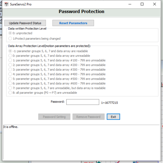
Use the radio buttons to set the protection status and parameter groups to be protected, then enter a password in the Password field and click Update Password Status. A password is now set for the chosen parameter groups.
Use PR Mode Simulation to test configured PR mode settings.

To run the PR mode simulation, make sure the servo is connected powered, then:
Check the Show current PR. Path checkbox. The dark green box at the far left of the toolbar should turn bright green (dark green offline mode pictured). If it doesn't switch to light green, verify communications with the servo.
Set a value in the text box next to Run PR. Path to set the PR path for testing. Possible values are:
0 = homing
1 - 99 = define which PR path to execute when Run PR Path is pressed. This is similar to using comms to write to parameter P5.007 or P5.112
Click Run PR. Path to execute the path entered into the neighboring cell. This is similar to using comms to write to P5.007 or P5.122.
Allow the test to run to completion, or click Stop PR. Path to halt the test.
If the test is completed unsuccessfully, the value in the far left green box will be the value of P5.007. If the test is successful, the value will be P5.007+10000. If DO.TPOS is ON (motor position reached), a successful test will display the value of P5.007+20000.
Use this wizard to complete the programming of the Indexing PR paths and relevant parameter settings.
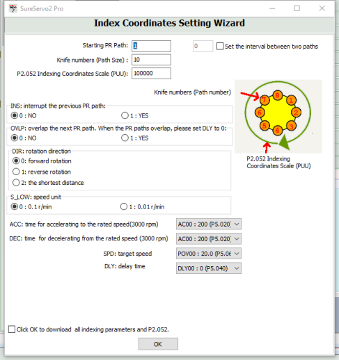
Set up indexing coordinates scale and total points.

Specify the knife number and indexing coordinates scale (PUU). These two values relate to the coordinates of each index point, where the path of each index is the PUU / Path Size. For example, if the indexing coordinates scale is set to 100,000 PUU and knife number (path size) is set to 10, the path of each index will be 100,000/10 = 10,000 PUU.
You can also set the start of the PR path to program the system with other PR paths by entering a value in the Starting PR Path field.
If you want to interrupt other PR paths between two indexing points, check Set the interval between two paths and enter a value to set the number of paths between index points. Use this option to insert statements (writes or conditional statements) or set DI/O between Indexing moves.
Setup related parameters such as indexing scale, rotation direction, acceleration/deceleration time and target speed.
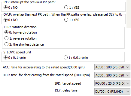
| Option | Function |
|---|---|
| INS | Allows the PR to interrupt the previous PR when executing. |
| OVLP | Allows the PR to overlap the next PR. When overlapped, disable DLY. |
| DIR | Sets the moving direction. Note that if you choose option 2: the shortest distance, shortest distance is determined by the current and target position. |
| S_LOW | Select the units for low speed movement. 0.1 r/min is the default, but if even finer control is needed, set to 0.01 r/min. |
| ACC | Set acceleration index using values set in Speed and Time Setting. |
| DEC | Set deceleration index using values set in Speed and Time Setting. |
| SPD | Set speed index using values set in Speed and Time Setting. |
| DLY | Set delay index using values set in Speed and Time Setting. |
You can now either write the related parameters to the servo drive, or close the wizard. To write to the servo, check the Click OK to download all index parameters and P2.052 checkbox, then click OK. Otherwise, just click OK.
There are four mode types configurable with the PR Mode Setting screen, all located in the left menu bar:
Speed and Time Setting: Acceleration/deceleration times, delay times, and target speeds are the basic settings when setting up a PR path. SureServo2 drives provide 16 sets of acceleration/deceleration times, 16 sets of delay times, and 16 sets of target speeds. These are shared for each kind of PR mode. See Speed and Time Setting for more details.
General Parameter Setting: Electronic gear ratio, software limit, deceleration time of protection and event On/Off setting are parameters that are commonly used when programming a PR path. See General Parameter Setting for more details.
Homing Setting: This setting is used to set the Homing path PR#0 that allows a machine to return to a user defined coordinate. Please see Homing Setting for details.
PR Mode Setting: PR mode is programmed using this setting. SureServo2 servo drives provide a built-in internal control mode (PR mode) that not only provides PR paths for users to execute single-axis motion, they can also issue commands based on speed control, position control, PR jump, and DI. PR mode supports 99 paths in total. Each one can individually program 5 different programming methods. See PR Mode Setting for more details.
This window is used to configure the parameters for each of the possible setting modes. Selecting an area in Setting the Mode determines the type of information that appears in the Main Settings Window.Use the dropdowns or type in values within the displayed ranges. Individual functions can be selected and written to the drive using Write This Path to Drive, or all changes can be written using Write All Paths to Drive.
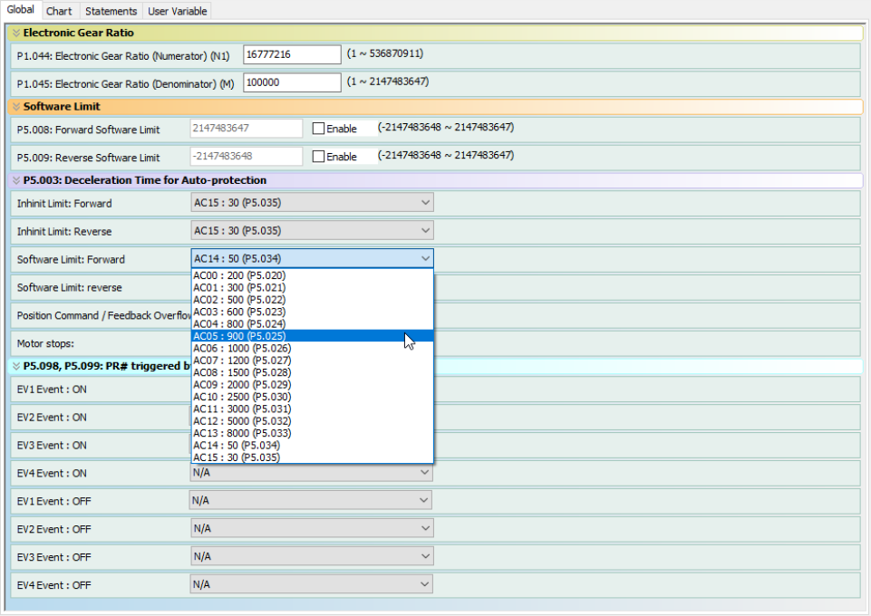
The Main Settings Window also contains three additional tabs:
The Chart tab provides a graphical representation of the PR paths created in the PR Mode window. The chart cannot be manually edited, instead it is generated automatically by the software to display the program flow of your paths.
Default Chart: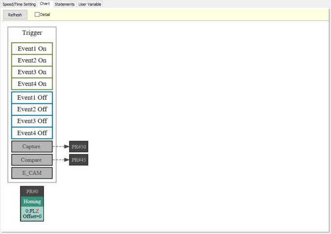
Programming Example: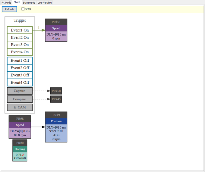
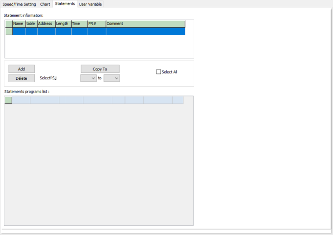
When creating a path, the last option for a path type is Statement. The Statements tab allows you to add and edit mathematical statements. Statements can be added here or in the PR Mode window. Any statements created in the PR Mode window will also be available here.
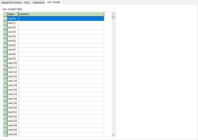
The User Variable tab is used to add, edit, or delete comments for the 64 user variables from PR Mode. These registers can be used in Statements or in the paths in the PR Mode window.
