When a machine is first powered up, it has no idea of the actual position of the axis. The servo drive may know the 0-360 degree position of the motor, but the position of the machine components (belt, knife, gripper, etc.) is unknown.
Homing is the sequence of events that lets the machine understand the position of all the motors and physical axes. Once a machine is “homed”, the servo and the machine controller know exactly where the axes are physically located.
Example: A servo motor is connected to a ball screw with a 10mm/rev pitch. Even though the servo drive knows that its motor is at 243 degrees (when the machine was first powered up), the drive has no way of knowing the location of the nut on the leadscrew. Homing will move the motor until a known reference point is seen (usually a proximity switch that senses the location of a part of the machine).
Homing in SureServo2 can be initiated in three ways:
1.) On power up of the drive
2.) By defining a DI as Enable Homing or SHOM (0x0027)
3.) By executing PR#0 (the Homing Path).
For SureServo2 systems with the encoder battery backup installed and Absolute Encoder configured (see Chapter 10 of the SureServo2 User Manual), Homing only has to be performed once – then the machine is always in a known position. For systems not utilizing the battery backup and Absolute Encoder mode, Homing may need to be performed each time the system is powered up.
Some applications never need to home: smooth conveyor belts (without lugs or “flights”), many web applications (the web position may be Captured with Registration, but the true position of the driving belt is unimportant), most Speed Mode applications.
Definitions
There are several definitions and acronyms used in the Software:
| Term | Definition |
|---|---|
| Homing Origin | The “zero position” of your machine. |
| ORG | This is the Homing Origin input (DI code = 0x0024). This is usually a proximity switch or limit switch located near the end of travel on a machine. Commonly referred to as a home sensor or home switch. |
| PL | Positive Limit (or Forward Inhibit Limit) of the machine. Can be a hard stop or a sensor (DI code = 0x0023). |
| NL | Negative Limit (or Reverse Inhibit Limit) of the machine. Can be a hard stop or a sensor (DI code = 0x0022). |
| Collision Point/Hard Stop | The physical end of travel for an axis. Example: when the nut on a ball screw hits the end of the assembly and can’t travel any further. Some homing modes intentionally look for this crash position during homing (usually, the motor torque is reduced in this mode). |
| Z-pulse | The zero-position of the motor. This is set at the motor factory and is not changeable. This is for fine-tuning the machine zero position (to within 1/16,777,216 of a revolution). If the resolution of the ORG Digital Input is repeatable/accurate enough, using the Z-pulse is not always necessary. |
| Origin Definition | The position the system considers "zero" or "home". You may not want the “machine zero” position to be 0. You may want it to be offset by some amount. Example: your home sensor on a linear ball screw assembly is approximately 1 inch from the end of travel. You may want to set your Origin Definition as the number of PUU units equal to 1 inch of travel. |
| High Speed Homing | Low Speed Homing: Some machines may have a long traverse. When homing is initiated, the motor will move at a High Speed in the commanded direction (toward the home sensor). When the home sensor is seen, the motor drops to the Low Speed. Homing continues at the Low Speed until complete (return to Home Sensor, find the motor Z-pulse, etc.). |
Example
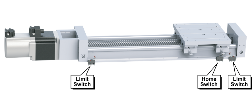
One of the best graphics to help visualize a servo’s homing routines is a linear actuator assembly. A rotary application will use the same sequences, terminology, and functions, but it is very easy to understand the concepts by looking at a linear application.

In this example, positive speed and positive incremental position moves result in the carriage moving left. Negative speed and negative incremental position moves result in the carriage moving right.
If issuing a positive command does not cause the carriage to move toward the PL Positive Limit sensor (the direction of motor rotation is opposite what you want), either swap PL and NL wiring or change the Rotation Direction of the system by changing P1.001:Z. (Must cycle power after changing P1.001.) If you have a rotary application or an application with no Overtravel concerns, you can use the other Homing Modes in P5.004 that do not involve PL and NL.
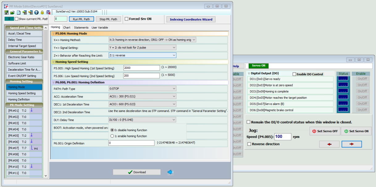
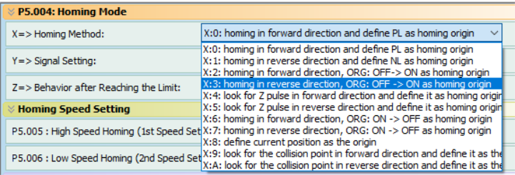
The options in P5.004 Homing Mode are very straightforward. One of the most common applications is to Home to the home sensor (ORG) and then continue until the motor Z-pulse is seen. To do this, select the following settings:

Notice that the Z setting is selected for “Reverse”. This is an important setting if there is a chance the sensor flag (the green piece on the carriage above) could be located between the ORG and NL sensors. If this happens when the Homing command is issued, the carriage would move to the NL (Overtravel) sensor, then reverse until it sensed the ORG (Home) sensor.

These set the speed the motor spins when Homing is commanded. The Low Speed Homing allows for more accurate/precise location determination (and has less deceleration when the sensor is found).

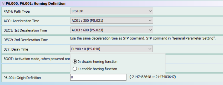
Other Homing Definition settings:

| Function | Description |
|---|---|
| PATH | After Homing is complete, you can command an additional Path to execute (if the machine normal starting position is not the same as Home Position). |
| ACC, DEC1, DEC2 | Standard acceleration and deceleration for the Homing moves. |
| DLY | Delay Time after Homing is completed before the next PATH is executed. |
| BOOT | Automatically Home on power-up or not. |
| P6.001 Origin Definition | After Homing is complete (and the motor has stopped), the current position is updated to the value in P6.001. The motor does not move to that position – the motor position is redefined as the value in P6.001. |
Tips for Using Homing
If Homing in FWD direction to the PL (Positive Limit), don’t choose “go forward to Z Pulse” after finding the home sensor (the motor can’t keep going forward when it is on the PL sensor).
If Homing in REV direction to the NL (Negative Limit), don’t choose “go forward to Z Pulse” after finding the home sensor (the motor can’t keep going forward when it is on the NL sensor).
When Homing to ORG, the motor will sense the Home position, decelerate, then return to the position it first saw the Home sensor.
For P5.004:X = 9 or A (Home to the collision point, aka hard stop), these settings should also be adjusted:
P1.087 Torque homing – torque level detection
P1.088 Torque homing – level reached timer
For an accurate and repeatable home position when using torque homing you should always home to a Z pulse after the collision point has been found.
To test and configure Homing on your machine, it is very efficient (in PR Mode) to use the PR Mode editor window and the Jog window at the same time. Use the Jog window to create various start-up scenarios (axis on the homing sensor, axis forward of the homing sensor, axis reverse of the homing sensor, etc.) to test your homing configuration. Example: jog the axis so that the ORG home sensor is ON, then click Run PR. Path 0 from the PR Mode window to see how your system responds.


