|
|
Topic: P329 |
Modbus Read/Write (MBUS) Instruction |
|
|
|
Topic: P329 |
Modbus Read/Write (MBUS) Instruction |
|
Icon / Button =

Perform Read or Write requests from the CPU to Modbus TCP Ethernet and Modbus RTU Serial Slave devices. This instruction is only available with P2-622 and newer (next-generation) CPUs. This instruction differs from the MRX/MWX instructions in that nearly all parameters can be modified on-the-fly, allowing a single instruction to address a large number of devices or registers, simply by changing a target IP address, slave node, or Modbus address before executing the instruction. It requires a Modbus device be configured in the Hardware Configuration window.
|
Parameter |
Parameter Type |
Requirements |
Description |
|
Enable |
Ladder Input |
Must Have |
Edge-driven. If Automatic Polling is selected, the instruction becomes Level-driven. When Enable is ON, the instruction will operate every scan. When Enable is OFF, the instruction is not solved, and its outputs are not updated. |
|
Use Structure |
Checkbox |
Optional |
Enables the use of a Structure for instruction tags. |
|
Modbus Device |
Drop-down |
Must select a |
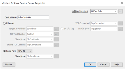
Pre-configured Modbus Devices will appear in this list. To add a new device, navigate to the Hardware Configuration window and select the Modbus tab, then drag Generic Modbus Device to the device area. A dialog will open and allow configuration. See Modbus Device Configuration for more details. |
|
Instruction Type |
Drop-down |
Must Select |
Select Modbus Read to request data from a device. Select Modbus Write to write data to a device. |
|
Polling Options |
|||
|
Automatic Polling |
Checkbox |
Optional |
The CPU will send out a request at the specified
|
|
Polling Frequency |
Numerical Tag |
Must have when Automatic Poling is selected |
How frequently the CPU will send a request to the specified device.(msec). |
|
Polling Offset |
Numerical Tag |
Must have when Automatic Poling is selected |
An offset, in msec, for the request to be delayed from the configured Polling Frequency. Multiple instances of this instruction, with the same frequency, can be configured however, the offsets must be different; the result being a ‘fanning out’ of these requests. This can alleviate communication load density. |
|
Skip Execution if Buffer is Greater Than |
Checkbox, |
Optional |
Used with Automatic Polling, allows the user to back-off an instruction if the buffer is getting too full. Set by a percentage. More details in the Communications topic. |
|
Instruction Status |
|||
|
In Progress |
Boolean Tag |
Optional |
Status Bit that specifies a Read Request is in progress inside of the CPU (sent from the instruction but not yet sent out the Ethernet Port). The Status Bit reflects the Status of the individual Read Request. |
|
Complete |
Boolean Tag |
Optional |
Status Bit that specifies a Read Request has been sent and a reply has been received, but it may not necessarily have been a good reply. The Status Bit reflects the Status of the individual Read Request. |
|
Success |
Boolean Tag |
Optional |
Status Bit that specifies a Read Request has been sent and a good reply has been received. The Status Bit reflects the Status of the individual Read Request. |
|
Error |
Boolean Tag |
Optional/p> |
Status Bit that specifies a Read Request has been sent and a reply with an Error has been received from the Slave device within the specified Timeout period. Check the Exception Response String to see if it's an Error returned from the Slave device or check the Error Logs to see if it is an Internal Error. The Status Bit reflects the Status of the individual Read Request. |
|
Timeout |
Boolean Tag |
Optional |
Status Bit that specifies a Read Request has been sent but no reply was received within the specified Timeout value time. Timeout value is set up in the External Ethernet Port and RS232/RS485 Serial Ports of the Hardware Configuration. The Status Bit reflects the Status of the individual Read Request. |
|
Exception Response String |
String |
Optional |
String that holds the exception response Error. View the Communication Error Codes section of the help file for detailed information on Error Codes and possible corrective actions. |
|
Addressing |
|||
|
Word Swap |
Checkbox |
Optional |
For 32-bit tags, the Lower and Upper words are Swapped when data is Read. |
|
Map 16-bit data to 32-bit |
Checkbox |
Optional |
Allows user to Map 16-Bit Modbus Addresses into the low Word of 32-Bit Tags in the CPU. |
|
Slave Modbus Starting Address |
Constant |
Must Have |
Modbus Starting Address of the Slave. |
|
Modbus Decimal Addressing |
Selectable Option |
Must Select Decimal or Zero Based Addressing |
Select if Slave Modbus Starting Address field requires the standard Modicon style Addressing format range from 1 to 65536. |
|
Zero Based Modbus Addressing |
Selectable Option |
Select if Slave Modbus Starting Address field requires the standard Modicon style Addressing format range from 0 to 65535. |
|
|
Modbus Function Code |
Drop-down |
Must Have |
Selects functions the instruction will Read (if Modbus Read mode is selected): 1:Read Coils 2:Read Input Bits 3:Read Holding Registers 4:Read Input Registers |
|
Selects functions the instruction will Write (if Modbus Write mode is selected): 5:Write Coils 6:Write Single Register 15:Force Multiple Coils 16:Write Multiple Registers |
|||
|
Mapping |
|||
|
Tag Mapping |
Selectable |
Must Have |
Selects the type of data the Modbus request will be written to or read from on the PLC: Non-Array: Allows data to be written to or read from non-sequential tags in PLC memory. Data on the Modbus slave device must be sequential. Array: Allows data to be written to or read from an array in PLC memory. String: Allows data to be written to or read from a string tag in PLC memory. Only even numbers of characters can be sent or received. |
|
Non-Array Mapping |
Automatically selected |
The Non-Array Mapping option is displayed when Non-Array is chosen as the Tag Mapping option. |
|
|
Number of Tags |
Constant |
Must have when Non-Array Mapping is selected |
Enter the number of tags to send or receive in the Modbus transaction. |
|
Tag |
Numerical Tag / Boolean Tag |
Array Mapping is selected |
Specifies the
Tags that will
Receive the
response, or Send the request.
|
|
Array Mapping |
Automatically selected |
The Array Mapping option is displayed when Array is chosen as the Tag Mapping option. |
|
|
Array Name |
Numerical Array Tag |
Must have when |
Specifies the Array that will Receive a response, or be the data source for a transmission |
|
Starting Index |
Integer Tag / Constant |
Starting position of the selected Array |
|
|
Number of |
Number of
Array elements that
will be filled by incoming data, or sent to a
Modbus slave
device • Max. 2000 for Boolean arrays • Max. 125 for 8-bit Integer arrays • Max. 125 for 16-bit Integer arrays • Max. 62 for 32-bit Integer arrays For Writes: • Max. 1968 for Boolean arrays • Max. 120 for 8-bit Integer arrays • Max. 120 for 16-bit Integer arrays • Max. 60 for 32-bit Integer arrays
|
||
|
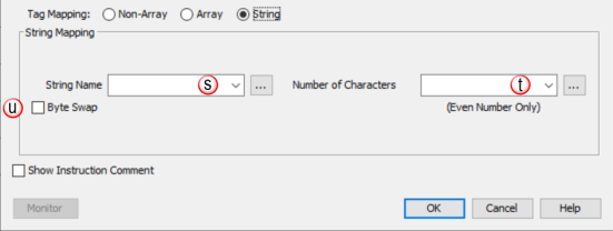
String Mapping |
Automatically selected |
The String Mapping option is displayed when String is chosen as the Tag Mapping option. |
|
|
String Name |
String Tag / Constant |
Must have when String Mapping is selected |
Specifies the String tag that will Receive a response, or is the source for a transmission |
|
Number of Characters |
Integer Tag / Constant
|
This value, whether a tag or a constant, must be an even number. Maximum value: 128 |
|
|
Byte Swap |
Checkbox |
Optional |
Every Two Characters will be Swapped when data is Read or Sent |
NOTE: This instruction is
only compatible with P2-622 and newer (next-generation) CPUs. On CPUs
with multiple ethernet ports and Port 2 (Remote) configured as
User Defined, when a selected Modbus device is configured
as an Ethernet device, communications are routed through the
appropriate port automatically, based on the target IP address and the
CPU’s gateway settings, if applicable.
Modbus devices
configured as Serial will communicate using the port selected and
node value configured in the Modbus device properties. The node
value can be changed throughout the program, and this instruction will
communicate using the node value at time of execution.
NOTE: During a runtime transfer any Modbus communications in operation will indicate a timeout bit. These will clear once the project transfer is complete.
When the Modbus Read/Write Instruction is selected the window shown below opens.
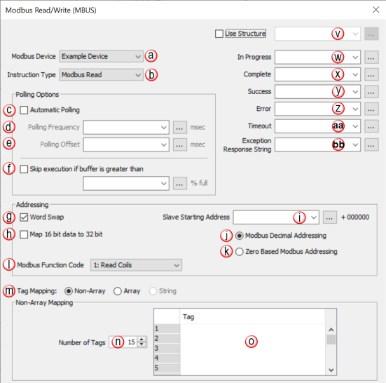
![]()
|
Parameter Configuration Table |
||||||||||||
Modbus Read/Write
|
|
|

|

|

|

|

|

|

|

|
Notes
*
|
|
|
|
Modbus Device |
Select a preconfigured Modbus device to target. This is set up in the Modbus tab of the Hardware Configuration window. |
||||||||||
|
|
Instruction Type |
Select Modbus Read or Modbus Write to match the intended instruction behavior. |
||||||||||
|
|
Automatic Polling |
Enable this checkbox to request a Read or Write action at a regular frequency |
||||||||||
|
|
Polling Frequency |
|
|
|
|
|
|
|
Enter the desired polling frequency, in msecs |
|||
|
|
Polling Offset |
|
|
|
|
|
|
|
Enter the desired polling offset in msecs |
|||
|
|
Skip Execution |
|
|
|
|
|
|
|
Select and enter % Value. |
|||
|
|
Word Swap |
Select if Word Swap is desired. |
||||||||||
|
|
Map 16-bit data to 32-bit |
Select if 16-bit to 32-bit conversion is desired. |
||||||||||
|
|
Slave Starting Address |
|
|
Enter a Starting Address for Slave Modbus. |
||||||||
|
|
Modbus Decimal Addressing |
Select desired Addressing |
||||||||||
|
|
Zero Based Modbus Addressing |
|||||||||||
|
|
Modbus Function Code |
Select desired Function Code The available options will change based on the Instruction Type. |
||||||||||
|
|
Tag Mapping |
Select the desired type of data to read or write |
||||||||||
|
|
Number of Tags |
|
Enter desired Tag(s) to be Mapped. |
|||||||||
|
|
Tag Table |
Enter a list of tags to populate from received data, or tags to send in one transaction |
||||||||||
|
|
Array Name* |
|
|
|
|
|
|
|
|
Enter Tagname of Array to be Mapped. |
||
|
|
Starting Index |
|
|
|
Enter the Starting Point of Mapped Array. |
|||||||
|
|
Number of Elements |
|
|
|
Enter the number of array elements to receive into, or send from. |
|||||||
|
|
String Name |
|
Enter the desired string Tagname to be Mapped for this Project. |
|||||||||
|
|
Number of Characters |
|
|
|
Enter the number of Characters to be read or written |
|||||||
|
|
Byte Swap |
Select if Byte Swap is desired. |
||||||||||
|
|
Use Structure |
Select if Structures are used. |
||||||||||
|
|
In Progress |
|
Select a Boolean Tag for Progress |
|||||||||
|
|
Complete |
|
Select a Boolean Tag for Complete. |
|||||||||
|
|
Success |
|
Select a Boolean Tag for Success |
|||||||||
|
|
Error |
|
Select a Boolean Tag for Error |
|||||||||
|
|
Timeout |
|
Select a Boolean Tag for Timeout |
|||||||||
|
|
Exception Response String |
|
Select a String Tag for Response Errors. |
|||||||||
To determine the total number of Modbus messages that can be sent per second (Ethernet throughput), use the following calculation:
Number of Modbus Masters/Slaves = 8
'Peak Scan Interval' System Tag = 10msec
8 x 10 msec. (100 scans) = 800 messages per second.
NOTE: The number and size of the tags used in a specific Modbus message will increase the scan time, thus affecting the overall throughput.


NOTE: Another side effect of
the queuing mechanism is the instruction status bits may not be seen in
the ladder. When an instruction has completed (Success, Exception Response, or Timeout), the CPU
firmware will set the appropriate status bits. At the point that the CPU
firmware pulls another message off the queue, it will reset the status
bits of that instruction. The timing can work out in such a way that the
status bits get set but the CPU firmware pulls off the instruction that
contains those same status bits and resets them to start another
iteration before the ladder code examines those bits.
Two things can be done to ensure reliable detection of status bits:
1. Do not use
Automatic Poll and instead
use interlocking logic to detect status completion of an instruction
before enabling that instruction again. This is the most reliable
method.
2. Ensure that the
Automatic Poll time is long
enough to prevent queueing of that same instruction.
See
Communications Modbus Functionality
help topic for more details.
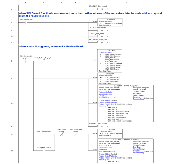
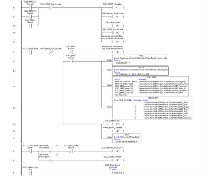
In the following example, the CPU TB serial port is to a number of SOLO temperature controllers using RS-485.