|
|
Topic: P243 |
Ladder Editor Window |
|
|
|
Topic: P243 |
Ladder Editor Window |
|
The Ladder Editor Window, also known as the Task Window or Task Pane, is the area where all program tasks are written using ladder logic programming and utilizing the more than 80 Boolean & Function Block style instructions.
By default you will see a “New Task” window open when you start a new project. This task is located in the Run Every Scan folder under the Task Management panel in the lower left of your default screen configuration.
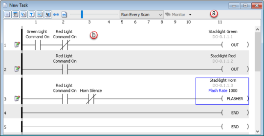
The Ladder Editor Window shown below is divided into two areas; the “Header” and the “Editor”.
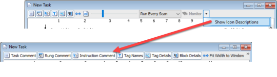
The drop down arrow to the right of the header icons provides the Show Icon Descriptions option. When selected, the Show Icon Descriptions option will populate the header with icon descriptions as seen below.
The following section describes each of these header options. Either scroll down to the desired option or click on any of the header options in the following diagram to view its detailed description.
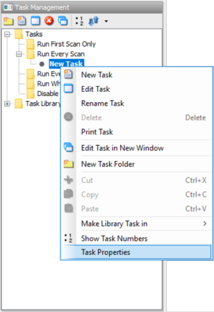
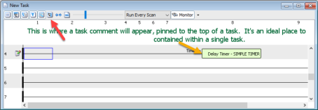
To add a Task Comment, right mouse click on the task you want to add a comment to and select Task Properties. Then enter your description into the Comment field of the Task Properties Window.
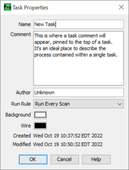
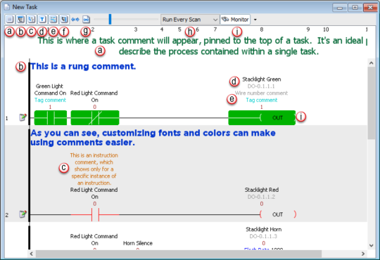
When Task Comment is selected, this comment will be displayed at the top of the task in the editor window.
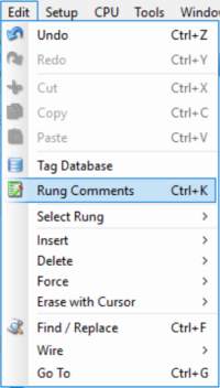
Rung Comment is a single comment for any given ladder rung in the program. The Maximum number of characters in this field is 512. This comment will only be seen in the specific task which you are currently editing. To add a Rung Comment, select the Rung Comment option in the header and then double left mouse click in between the rungs to open the Current Rung Comment editing box.
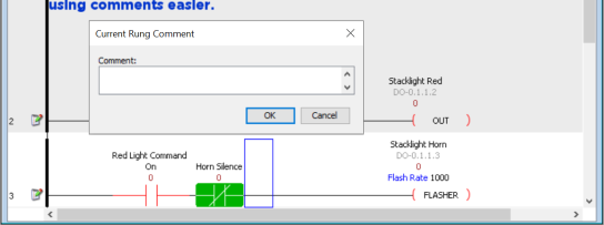
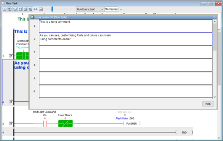
When the Rung Comments editor is opened, the Task name will be shown in [brackets] on top of the editor window as seen below. The numbers in the left column correspond to the rung numbers in your task. The blue high-lighted field in this editor represents the rung location of your cursor when you opened the rung comments editor window.
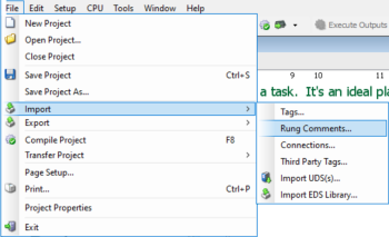
In order to simplify your documentation process even further, you can import your rung comments in a .csv file format by selecting the File Menu > Import > Rung Comments.
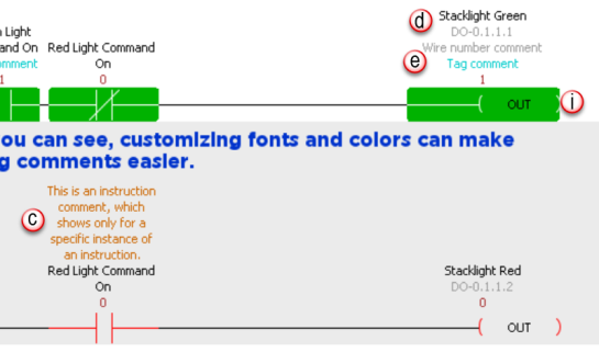
To add an instruction comment, enable the comment field of the instruction by selecting the Show Instruction Comment option.
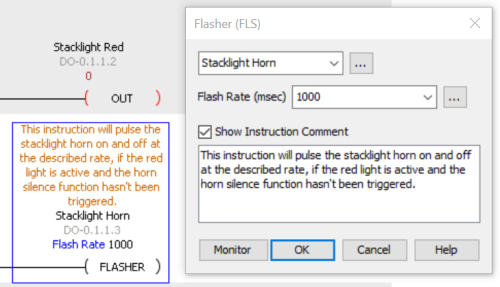
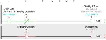
With Instruction Comment selected in the Header, the comments added to the instruction will be displayed in the Ladder Editor as seen below.

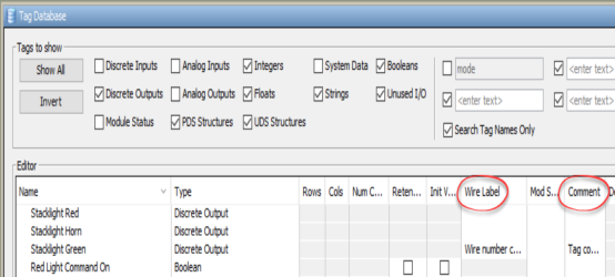
Tag names are descriptive and defined by you, the user, so they make sense to you for the application you are designing. The following table shows that when comparing this system to a fixed memory addressing system there are clear advantages.
|
Variable |
Fixed Memory Addressing |
Tag Name Addressing |
|
Discrete Input Point |
X135 or I:003/15 |
Conveyor1.Part Present.PE |
|
Internal Boolean |
C45 or B3/45 |
Conveyor1.Auto.Enable |
|
Temperature Input |
V2200 or N7:15 |
Oven1.Zone3.Temp |
|
Discrete Output Point |
Y100 or O:004/1 |
Oven1.Combustion Blower.ON |
(addresses are for example purposes only and have no relative representation from PLC to PLC)
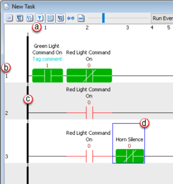
Selecting the Tag Names option in the Header section will display the tag names in the Ladder Editor (seen as bullet d in the diagram below).

(user defined tag name)
(default tag name for discrete inputs & outputs)
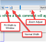
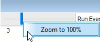
- To quickly restore zoom to 100%, right-click on the slider and select 'Zoom to 100%'.

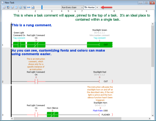
- The contacts and coils will be highlighted with either a red or green color.
- A numerical 1 or 0 (1=On, 0=Off) will be displayed above the contact or coil indicating its binary state.
Note: There are
16 groups containing
64 tags each (1024
total tags) available for
Data View and
Data Monitor to share.
For example: If the number
of visible tags in
Data View and each of the
task windows does not exceed the limit of
64 tags, there can be a
total of 16 task windows, or
15 task windows with
Data View, monitoring at the
same time. Once the 64-tag
limit is reached in one group, the set of tags are split into multiple
groups and the number of available monitoring windows starts to
decrease.
In addition, array element tags use a different set of groups from the
regular tags with the same maximum number of groups and the same maximum
number of tags in each group.
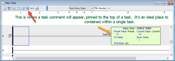
Monitor Mode also enables the viewable tag values in the function block instructions. The following diagrams show the effects of monitor mode on the ladder editor.
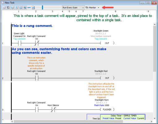
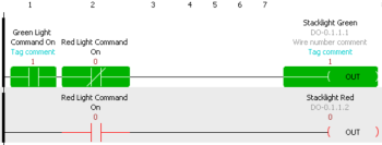
Monitor mode offers two display options. The default (shown below) reflects the various states of the contacts and coils with Green (ON) or Red (OFF) line color. This option may be preferable when programming and troubleshooting on a desktop.
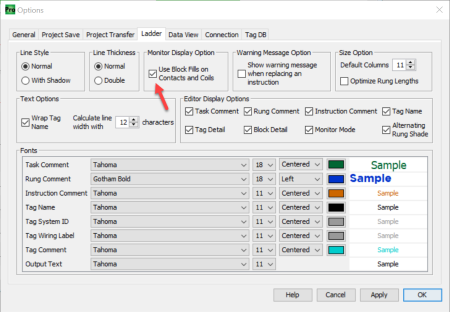
The second option, known as Block Fill, can be selected from the Tools Menu > Options > Ladder Tab > Monitor Mode Display State Options. This option will reflect the varying states with Green (ON) fill or Red (OFF) line color for your contacts & coils. This option makes viewing the states of your logic much easier on plant floors and when monitoring the logic from a distance.
The Editor area is where the Ladder Logic program code is written, edited and monitored. There are four major areas to the Editor.
Note: The last column on the ladder rung is where all output coils and function block instructions must reside.
Note: Maximum number of input columns is limited to 127 & output columns 1.
Note: The maximum number of rungs allowed per task is 4096.
The Power Rail is the dark main line on the left most side of every rung. This is the starting point for every rung and indicates separation from rung to rung with a minor separation in the power rail (not a complete break).
The Cursor Position is indicated by a blue line square.
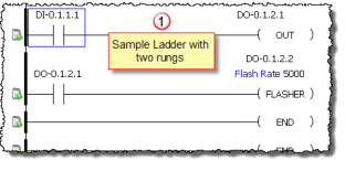
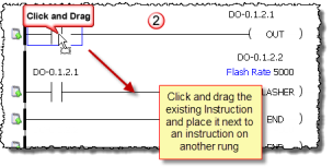
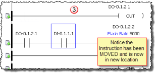
Productivity Suite Software allows the ability to drag already placed instructions in ladder and drop them into to another location in the same ladder window.
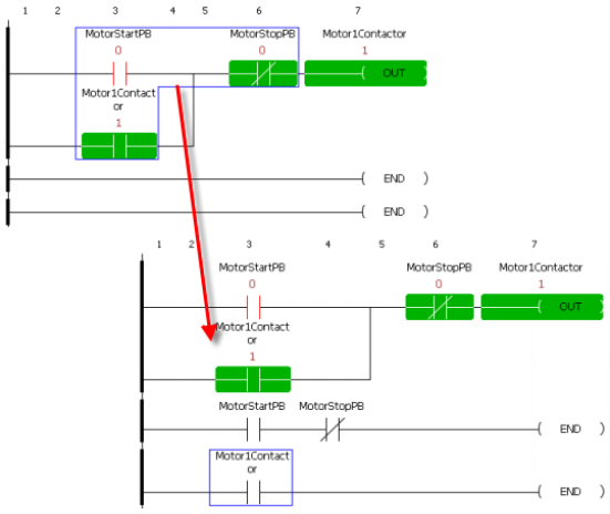
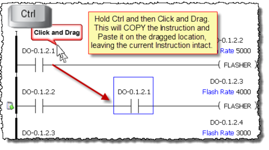
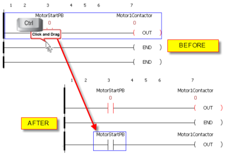
All of the above apply for this section. However, by pressing and holding the "Ctrl" key while clicking and dragging the Instruction, a Copy of the selected Instruction will be made and dropped into the location where it is dragged to in the same ladder window.
Note: Ctrl+Click can also be used to expand or reduce a selection one adjacent element or section at a time. Ctrl+Click a non-adjacent element or section will reset the selection to what has just been clicked. Shift+Click or Shift+Arrow Key can be used to select a range of rungs, elements, or sections.
Note: Copy and Paste of partial rungs will insert the partial rungs at the selected paste location and shift existing elements on that rung down to new subrungs, as needed.
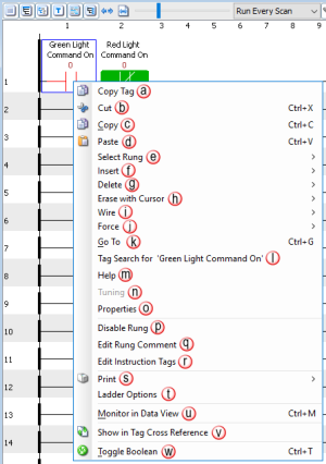
Right-Click on any Instruction in the Editor window and a convenient popup menu will appear that provides a number of shortcuts to quickly access software features related to the Instruction.