|
|
Topic: P341 |
User Defined Instruction |
|
|
|
Topic: P341 |
User Defined Instruction |
|
UDI functions are similar to function blocks in other programming environments; allowing users to define custom instructions tailored to their specific automation needs. These instructions help streamline programming by encapsulating commonly used logic into reusable, self-contained modules.
|
Parameter |
Parameter Type |
Requirements |
Description |
|
Enable |
Ladder Input |
Must Have |
Level-driven. When Enable is ON, the instruction will operate every scan. When Enable is OFF, the instruction is not solved and its Outputs are not updated. |
|
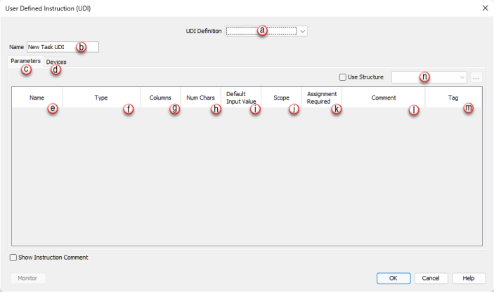
UDI Definition |
Dropdown Selection |
Must Have |
A UDI definition must be created in the UDI Management panel for this instruction. Once UDI definitions have been created, they can be selected in this field. |
|
Name |
Assigned from UDI definition editor window |
Must Have |
Allows the user to give a unique name (maximum 32 characters) to each UDI instruction instance for easier reference. *See Note 1 below |
|
Parameters |
|||
|
Parameter Name |
Assigned from UDI definition editor window |
Dependent on UDI configuration |
Displays the parameter name (defined in the UDI Definition Editor panel). |
|
Type |
Assigned from UDI definition editor window |
Dependent on UDI configuration |
Indicates the parameter data type (defined in the UDI Definition Editor panel). |
|
Columns |
Assigned from UDI definition editor window |
Dependent on UDI configuration |
Indicates the number of columns defined for an array parameter (defined in the UDI Definition Editor panel). |
|
Num Chars |
Assigned from UDI definition editor window |
Dependent on UDI configuration |
Indicates the number of characters defined for string parameters (defined in the UDI Definition Editor panel). |
|
Default Input Value |
Assigned from UDI definition editor window |
Dependent on UDI configuration |
Indicates the default beginning value (defined in the UDI Definition Editor panel) of a parameter when the UDI is executed, if it does not have a tag assignment. This only applies to parameters with Local, In or In/Out scope. *See Note 2 below. |
|
Scope |
Assigned from UDI definition editor window |
Dependent on UDI configuration |
Indicates how the parameter is used (defined in the UDI Definition Editor panel). Possiblescope selections are In, Out, In/Out, and Local. |
|
Assignment Required |
Assigned from UDI definition editor window |
Dependent on UDI configuration |
Indicates whether a Tag or value must be assigned to the parameter (defined in the UDI Definition Editor panel). |
|
Comment |
Assigned from UDI definition editor window |
Dependent on UDI configuration |
Use this field to add Comments associated with the parameter. |
|
Tag |
User Selectable |
Must Have/Optional |
This field allows the user to assign Tags or static values for the UDI parameters. If a parameter requires assignment, then a Tag or static value must be entered in this field. |
|
Use Structure |
Selectable Option |
Optional |
Enables the use of Structure for elements of the chosen UDI definition. Select from dropdown list of available structure names or enter name to create a new structure. |
|
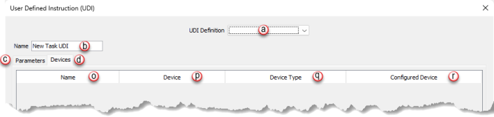
Devices |
|
||
|
Name |
Assigned from UDI definition editor window |
Dependent on UDI definition |
Indicates the name of the device (defined in the UDI Definition Editor Window). |
|
Device |
Assigned from UDI definition editor window |
Dependent on UDI definition |
Indicates the device definition assigned (defined in the UDI Definition Editor Window). |
|
Device Type |
Assigned from UDI definition editor window |
Dependent on UDI definition |
Indicates the specific type of device assigned (defined in the UDI Definition Editor Window). Not all devices will have a Device Type defined. |
|
Configured Device |
User Selectable |
Dependent on UDI definition |
This field allows the user to choose from the list of available devices that have been defined in the project Hardware Configuration that matches the UDI device.. |
Note 1: Can contain only a-z, A-Z, 0-9, hyphens, underscores, and spaces.
Note 2: Default value is only available if not marked as assignment required.
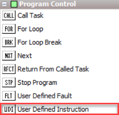
The User Defined Instruction (UDI) is located on the Instruction Panel under the Program Control section.
When User Defined Instruction is selected the window shown below opens.
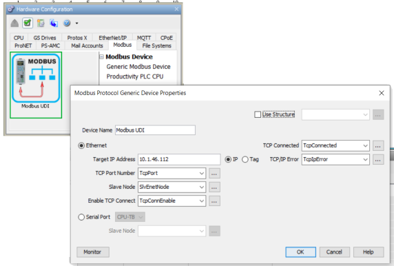
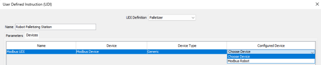
Note: A configured device must already be set up in Hardware Configuration to associate the UDI Device to a device in the project.


 or
or  These icons indicate to use 1D and/or 2D Array data types as indicated in Data Type column.