Topic: P339

UDI (User Defined Instruction) Definition Editor

Icon / Button =

Purpose

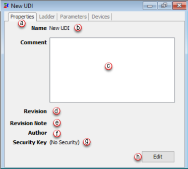
UDI (User Defined Instruction) definition editor panel is where users can create, edit, and configure a UDI Definition that can be instantiated in ladder using the User Defined Instruction.


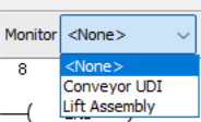
The User Defined Instruction editor window can be accessed by double clicking on a specific UDI definition in the management panel.

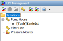
Note: Each bold text item below the UDI definition name is associated with the location of an instance of the User Defined Instruction in a ladder task. Double clicking on the Instance Name will navigate you to that section of ladder logic. For the example shown, there is one instance of the Pump House UDI in the Tank task on Rung 1.

UDI Management

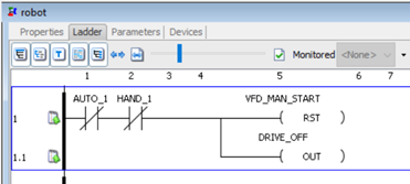
If parameters with the same name but different data types are already existing in the UDI Definition, the newly copied and pasted instruction(s) will be appended with a “_1”.

  1. Rename: To rename a UDI definition, either double click on the name of the instance, which brings up the properties window (next image below), then select edit; or right click on the instance and select Rename. A maximum of 32 characters is allowed.

  2. Delete UDI: To delete a UDI definition, select the definition and press the Delete key or right click on the name of the instance and select Delete.


UDI Properties Window

  1. Properties tab: The properties tab contains the information associated with the UDI definition. This information was entered when the definition was created. This tab can be used to view or update that information.
  2. Name: Name of the UDI definition. Maximum of 32 characters allowed.
  3. Comment: Enter comments that are pertinent to or helpful in describing a UDI definition. Maximum of 1024 characters allowed.
  4. Revision: The revision is not automatically managed by the software. The user is responsible for defining how it is used and when it is updated. A maximum of 32 characters are allowed for Suffix field.
    1. Example: The Revision will read as “1.0revA” when the user enters a 1 in Major, leaves the Minor as 0, and types “revA” into the Suffix field.”
  5. Revision Note: Enter information that is pertinent to changes made in the revision. Maximum of 1024 characters allowed.
  6. Author: Name or initials to identify the author of this definition. Maximum of 64 characters allowed.
  7. Security Key: Lists of the available security keys that are configured in the UDI Security Management setup.
  8. Edit: Clicking the edit button allows the user to edit the definition properties.

Ladder

Note: Nesting of up to 4 UDI definitions is supported.

  1. The Ladder tab is used for creating the UDI ladder logic. More than 80 Boolean and Function Block style instructions are available to create the UDI, in the same manner as a Task in the Main Project. See below note for disallowed instructions.
  2. Task Comment is a single comment used to provide a general description for the entire task in question. The maximum number of characters allowed in this field is 2048. This will only be visible in the specific task that you are currently editing.
  3. Rung Comment is a single comment for any given ladder rung in the program. The Maximum number of characters allowed in this field is 512. To add a Rung Comment, select the Rung Comment option in the header and then double left mouse click between the rungs to open the Current Rung Comment editing box.
  4. Instruction Comment is designed to give the user specific details regarding this instance of this instruction. This is not a global comment and does not pertain to other instances of this instruction or the tags contained within the instruction, but rather describes the action performed by this specific use in its current location. To add an instruction comment, enable the comment field of the instruction by selecting the Show Instruction Comment option.
  5. Tag Names are the descriptive name of each Parameter as defined by the user in the Parameters tab.
  6. Tag Details show the defined Comments for each Parameter.
  7. Block Details allows the user to view or hide the details within the ladder instructions. This option applies to all block instructions within the current UDI definition being viewed.
  8. The Fit Width to Window button gives the maximum viewing perspective for the current window size and display resolution, while keeping the complete ladder rungs in view.
  9. Normal Width button will return the zoom level to the default 100%.
  10. Zoom Scale ranges from 33% to 300% in viewing perspective. The slider bar allows for easy adjustment and the mouse over feature gives a user the exact zoom value of the current view.
  11. Validate is used to check new or edited ladder for any errors.
  12. Monitored gives the user a graphical representation of the logical state of tags as they appear in the ladder logic. From the drop down choose from the list of available instances.
    1. Select the drop down to choose the UDI instance to monitor.

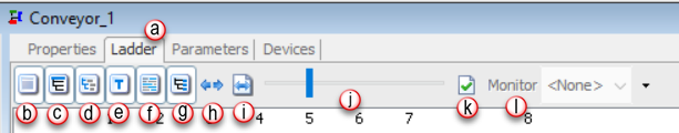
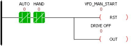
      These logical states are represented in two ways:

      The contacts and coils will be highlighted with either a red or green color.

      A numerical 1 or 0 (1=On, 0=Off) will be displayed above the contact or coil indicating its binary state.


Items not Supported

There are several items that are not supported in UDI Definitions.

Unsupported Communication Instructions

AIN

AOUT

CPI

VMW

CPO

MRX

MWX

RX

WX

NETW

GSR

GSW

DWX


Unsupported Program Control Instructions

CALL

ACLR

RFCT


Unsupported High Speed I/O Instructions


* All High-Speed Functions

Unsupported PID Instructions

PID


Copy and paste from other ladder tasks


Copy selected rung(s) from another task or UDI Definition and paste into the ladder editor window.


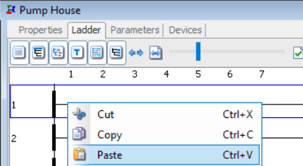
If parameters with the same name already exist in the UDI Definition, the newly copied and pasted instruction(s) will be appended with a “_1”.


Parameters 


  1. Name: Name of the parameter. The length can be from 1 to 32 characters.
  2. Parameter Type: Use the Data Type Class radio buttons to display Internal, System Structure, User Structure, or UDI Structure data types. The Add Parameters window defaults to Internal Type. The Data Type is further defined in the Data Types topic.
  3. Columns: Active with 1D Data Type. Enter the number of Columns required in the Array.
  4. Characters: Active with String (Basic & Array) Data Type only. Enter the number of Characters the string parameter can contain. Maximum is 128, default is 15.
  5. Default Value: When assignment of a parameter is not required and the parameter is not assigned a value, the default value is assigned to the parameter on CPU switch from stop to run.
  6. Scope: The parameters define the instruction interface; that is, how the instruction appears when used. The parameter order defines the order that the parameters appear on the instruction call.
    1. Local: A local parameter is a variable that is defined within the UDI definition and only accessed by the UDI function itself. A local parameter does not have an In, Out, or InOut assignment.
    2. In: Data that is passed by value into the UDI for processing. During the execution of the UDI, the value cannot be changed by sources external to the function.
    3. Out: Data resulting from the execution of the UDI. The data returned from the UDI is passed by value and cannot be changed by sources external to the function during the execution of the UDI.
    4. In/Out: Data that can serve as both input data and output data during the execution of the UDI. InOut parameters are passed by reference and can be changed by sources external to the function during the execution of the UDI.

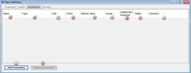
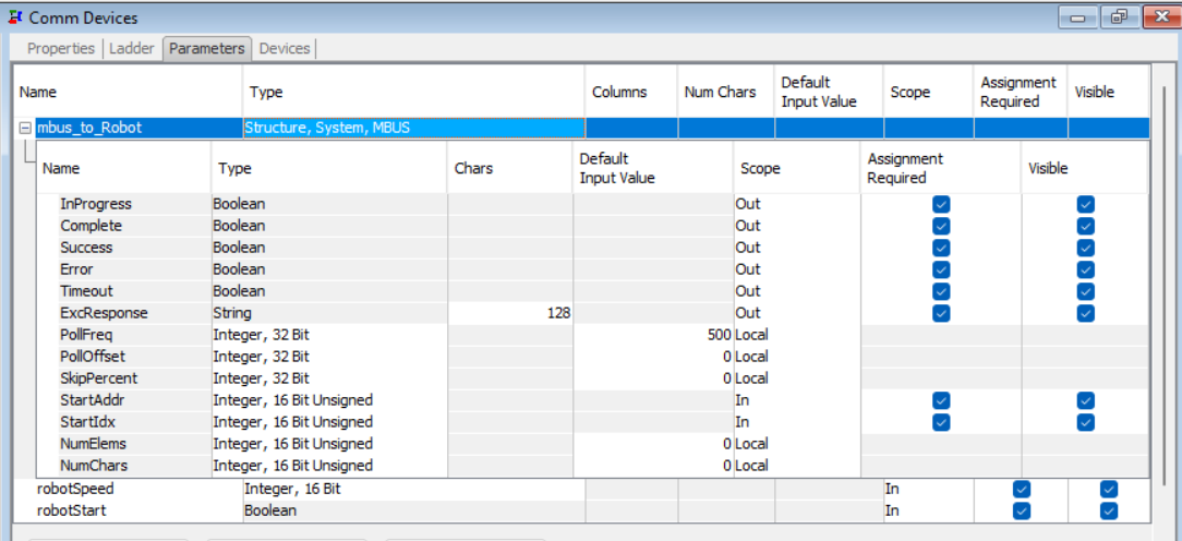
    Note: Expanding a pre-defined (PDS) and user-defined (UDS) structures will allow a user to set the scope for each individual element.

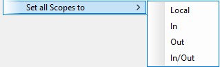
    Note: Right click on a PDS column header allows option to become available for setting all scopes, assignment required, and visible to available options.

    Example


  1. Assignment Required: Determines if a parameter must be assigned a tag or constant when the UDI is instantiated in ladder. This will help ensure that specific data is passed into the UDI, i.e. I/O tags, or data and setpoints from the main task.


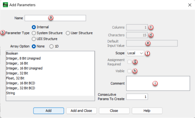
    Note: Not applicable to Local Tags which cannot be assigned.


  2. Visible: Determines if the parameter is visible in the UDI instruction object in ladder.


    Note: This will allow the user to view parameters that are not required but may be useful to view in UDI instruction for troubleshooting.


    Note: Not applicable to Local Tags which cannot be visible.


  3. Comment: Enter a comment to describe the parameter. A maximum of 80 characters is allowed.


Devices

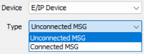
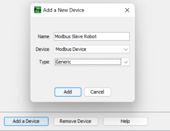
Virtual hardware devices are required for some instructions, such as EMSG, to be used in the UDI. The Devices tab allows the user to add a virtual hardware device that the instruction(s) in the UDI definition ladder are able to reference.
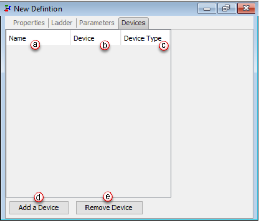
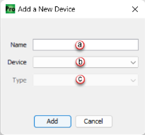
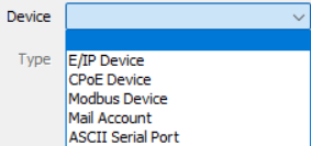
  1. Name: The name of the virtual hardware device.
  2. Device: Choose from the dropdown menu the device type to be assigned.

  3. Device Type: Gives the user the ability to choose from the dropdown the device type to be assigned. The options will vary depending on the device chosen.


    Example


  4. Add a Device: Select to add a new device.
  5. Remove a Device: Select to delete a device.


Steps to create and use a device in a UDI: (Modbus Device example)

  1. Select Devices tab in the UDI definition and add a Modbus Device..

  2. Once the device has been added, go to the ladder tab. Add an MBUS instruction, selecting the Modbus Device that was just added to the UDI definition.
  3. In the Parameters tab, set up data types and scope for each parameter.

Creating a UDI Definition from the Task Library

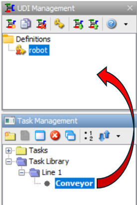
There are two ways to create a UDI definition from a task in the Task Library.

Method 1: Drag a task from the Task Library and drop it into the UDI management panel.

Note: Any unsupported instructions or 2D arrays references must be removed first prior to adding from Task Library.

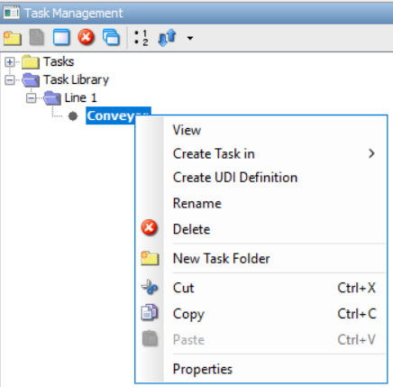
Method 2: Copy and paste a task from the Task Library into the UDI Management panel.


Note: If a task from the library is moved into a task folder that contains a task with the same name, then a copy will be generated and a _1 will be appended to the task name.


Note: When moving a task from the library, any tags with names that already exist in definition parameters will not inherit any attributes and be set to local scope.


Note: If a task from the library is moved into a task folder that contains a disallowed instruction an error will be displayed listing that instruction.


Related Topics:

Related Topics Link IconRelated Topics