Topic: CL349

| Flasher Out Coil |
Topic: CL349
|
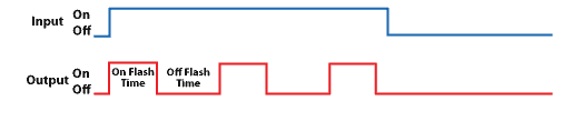
The Out Flasher instruction turns the output Bit Memory Address On and Off repeatedly at a specified rate while the rung is enabled. The On Flash Time and Off Flash Time are both required and can be configured independently, allowing different On and Off durations. When the rung goes false, the output turns Off immediately regardless of where it was in the flash cycle.
Two Timer Current Value (TD) registers are used/consumed by each Out Flasher instruction, one for the On Flash Time and one for the Off Flash Time.
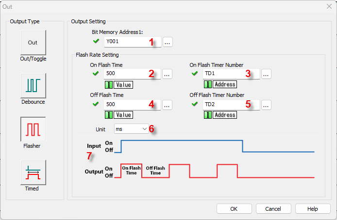

1 Bit Memory Address 1: Choose a Bit Memory Address to associate with the Out instruction. Either type the Bit Memory Address directly in the address field or use the Browse Button to open the Address Picker.
2 On Flash Time: Assign Data Memory Address to hold the On Flash Time value or a Constant. DS is the only eligible Data Memory Address range.
3 On Flash Timer Number: Assign a Timer Current Value (TD) Register to be used for the On Flash Timer Number. TD is the only eligible Data Memory Address range.
4 Off Flash Time: Assign Data Memory Address to hold the Off Flash Time value or a Constant. DS is the only eligible Data Memory Address range.
5 Off Flash Timer Number: Assign a Timer Current Value (TD) Register to be used for the Off Flash Timer Number. TD is the only eligible Data Memory Address range.
6 Unit: Assign the time measurement Units using the Drop Down List (ms, sec).
7 Input / Output Timing Chart: The Timing Chart displays the functionality of the instruction
Example Program: Flasher Out Coil
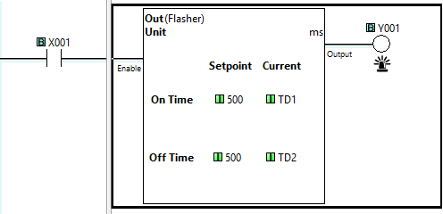
In the following example, when input status of bit X001 is On, output bit Y001 will be On for 500ms then Off for 500ms, cycling between On then Off. When input X001 bit goes Off, Y001 will go Off immediately as well.
Out Coil
Debounce Out Coil
Timed Out Coil
Set Coil
Reset Coil