Topic: CL243

| PID Configuration Mode |
Topic: CL243
|
The CLICK Ethernet PLC is capable of supporting up to 8 PID Control Loops. For more information on how PID is implemented in the CLICK PLC, see Help topic PID Control in CLICK.
A PID control loop is a continuous feedback loop that uses the error between a Setpoint (SP) and a Process Variable (PV) to determine the value of a Control Output (CO). The SP is usually an operator-entered value and is the desired value of the PV. The PV is usually an Analog Input to the PLC and is a measured value in the Process being controlled. The PV may be a flow rate, pressure, temperature or process variable that can be measured by process instrumentation. The CO may be a control valve position, a damper actuator position, a variable speed drive speed setting, etc.
When the SP is changed or a disturbance in the process causes the PV to change, an error occurs between the SP and PV. The PID Control uses Proportional, Integral and Derivative terms with the error to determine the CO that will return the PV equal to the SP.
Each PID Loop requires consecutive C, DS and DF memory areas. All PID Loop Configuration parameters are stored in these memory locations.
Tools in the Configuration dialog will assist in selecting available consecutive addresses for each.
The PID Configuration Mode dialog is used to configure each PID Loop. In this dialog you can find available addresses for the PID Loop parameters. You can also Read and Write PID Loop configuration values to an existing PID Loop configuration in a connected CLICK PLC.
To set up a PID Control Loop, from the Menu select Setup> PID Setup. Alternately, from the Program tab, double-click PID Setup.

The General tab opens. By default, the first PID Loop Name to be created is PID001. This can be changed at any time.
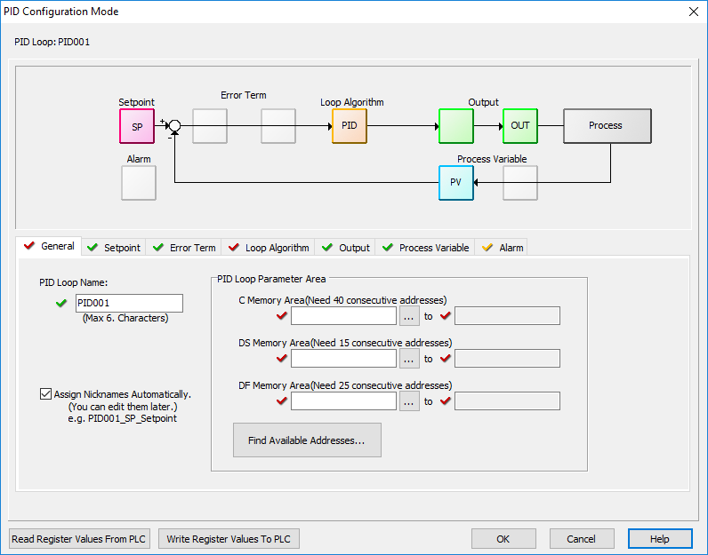
PID Loop Name: The PID Loop Name can be a maximum of 6 characters.
Assign Nicknames Automatically: The PID Loop Name will be appended to the beginning of all of the Nicknames for the Memory addresses associated with this PID Loop. For example, PID001_SP_Setpoint. These may be edited later.
Read Register Values From PLC: Click this button to read all the registers associated with the current PID Loop into the PID Configuration dialog.
Write Register Values to PLC: Click this button to write all of the PID Configuration Registers in the PID Configure dialog into the PLC memory locations configured in the PID Loop Parameter address.

|
Note: Best practice is to first Read the Register Values from the PLC before selecting to Write Register Values to the PLC. |
Each PID Loop requires consecutive C, DS and DF memory areas. All the PID Loop Configuration parameters are stored in these memory locations.
C Memory Area - 40 Consecutive Bits
DS Memory Area - 15 Consecutive Integers
DF Memory Area - 25 Consecutive Floats
In the other tabs in the Configuration dialog box, the address assigned will be shown next to each parameter. Throughout this Help file, the beginning address for each address range is symbolized as Cn, DSn and DFn.
Select the Memory Areas in one of two ways:
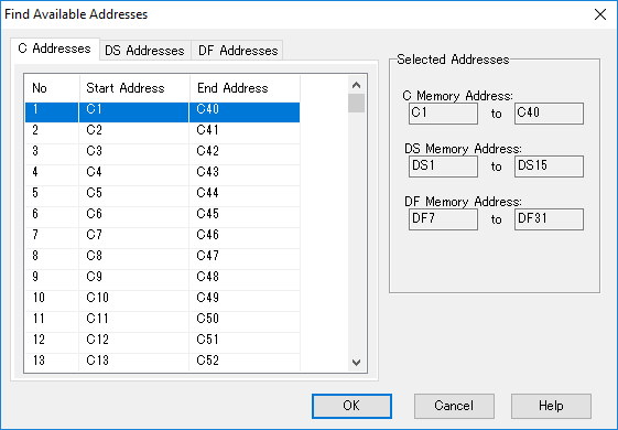
- The best option is to let the software select the address for you from the available unused addresses by clicking the Find Available Address... button. The Find Available Addresses dialog allows you to select which range of addresses you want to use for each memory type with the present PID Loop configuration from the "available" addresses.
- In the General tab you can select the beginning address for each Memory Area and the software will automatically allocate the number of addresses for the PID Loop. Care must be taken not to select a range of addresses already used in the PLC program for another purpose.
See the Help topic PID Address Descriptions for a full list of the addresses and nicknames assigned for each PID Loop configuration parameter.
The Setpoint (SP) (DFn+00) is the value to which the PID Control Loop is trying to drive the Process Variable (PV).
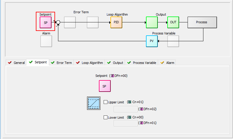
Setpoint Upper and Lower Limits: You may select to limit the allowed upper and lower settings for the Setpoint. This is useful in preventing someone from accidentally entering a value that is outside the process limits.
When enabled, if a Setpoint value is entered outside of the limits, the PLC will automatically change the Setpoint to the limit that is closest to the value entered.
The limits are enabled individually:
Upper Limit enable (Cn+01)
Lower Limit enable (Cn+00)
The limit values must be set if the limit is enabled:
Upper Limit value (DFn+02)
Lower Limit value (DFn+01)
The Error is the difference between the Setpoint (SP) and the Process Variable (PV). Error = SP - PV.
The Error Term tab is used to select from a couple of ways the Error can be manipulated to better control certain processes. To use the Error as is, leave both options off.
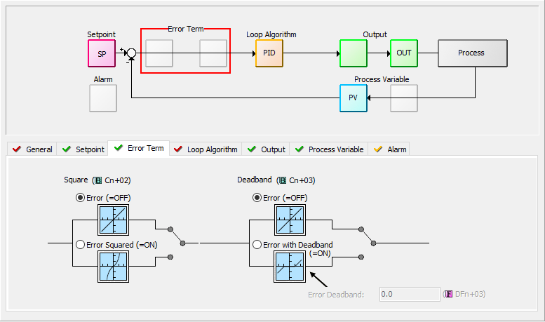
When the Error Squared (Cn+02) option is selected, the error term is squared (preserving the original sign), before it is used in the PID calculation. This lessens the response to smaller error values, but increases the response to larger errors.
When the Error with Deadband (Cn+03) option is selected, no control action is taken if the Process Variable (PV) is within the specified Error Deadband (DFn+03) around the Setpoint (SP). The error deadband is the same above and below the SP and is in the same units as the PV and SP.
Once the PV is outside of the error deadband around the SP, the entire error is used in the loop calculation.
If Error Squared is enabled, the error will be squared before it is applied to the deadband calculation.
The Loop Algorithm tab is the heart of the PID Loop setup.
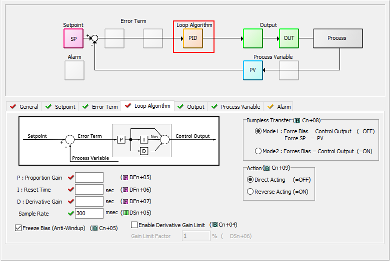
The PID calculation utilizes the following parameters and equation. The P, I and D are often referred to as "Tuning Parameters" because their values affect the responsiveness and stability of the control loop. Incorrect tuning parameters can lead to an unresponsive, oscillatory or unstable (out of control) process loop. There are many resources available about tuning PID control loops.
P: Proportional Gain (DFn+05) ( 0.01 - 10000)
I: Reset time (DFn+06) (0.01 - 6000 seconds)
D: Derivative Gain (DFn+07) ( 0 - 6000 seconds)
The P, I and D parameters as well as the Sample Rate can be set automatically by using the Autotune features of the CLICK PID. See the PID Autotuning Help topic for more information.
Range: 100 - 30000 ms
The PID control is performed as part of the Main Program, but the new CO is calculated when the sampling rate time has elapsed.
Freeze Bias, also known as Anti-Windup, is a feature of the CLICK PID that can make your process more stable and recover more quickly from process disturbances. See the Help topic PID Control in CLICK for more information about this feature.
Range: 1 - 100
The Derivative Gain Limit (Cn+04) is a high frequency filter for the Derivative Gain. With it you can limit the effect that high frequency noise has on the Derivative portion of the calculation.
The Gain Limit Factor (DSn+06) can be 1 to 100, although a value from 8 to 20 is more typical. A value of 100 will essentially apply no filter to the Derivative. As the Limit is reduced, the effect of PV noise on the Control Output is reduced. A value of 0 is the same as setting the Derivative Gain to 0.
The Action (Cn+09) of a control loop is either Direct acting or Reverse acting. It is important to know in which direction the control output will respond to the error.
A Direct acting control loop means that whenever the control output increases, the PV will also increase. For example, if the Control Output drives open a gas valve to a flame control, the Temperature will increase as the Control Output increases.
A Reverse acting control loop is one where an increase in the control output results in a decrease in the PV. A common example of this would be a refrigeration system, where an increase in the cooling input causes a decrease in the PV (temperature).
A Bumpless Transfer (Cn+08) refers to the method of switching from Manual Mode to Auto Mode without causing a "bump" in the process by sudden movement of the Control Output.
Mode 1(ON): Accomplishes no bump because the SP and PV are made equal, requiring no immediate change in the Control Output.
- The Bias Term is made equal to the Control Output.
- The SP is made equal to the PV.
Mode 2(OFF): Since the SP is not made equal to the PV, a bump in the Control Output can occur when the control is switched from Manual to Auto. It is up to the Operator to make changes to the process settings to prevent a bump in the process.
- The Bias Term is made equal to the Control Output.
The Control Output (CO) (DFn+08) is the result of the PID calculation. It is usually tied to a physical output on the PLC, which is wired to a control device such as a valve actuator.
The Control Output is Read Only when the loop is in Auto. To change the Control Outout, the loop must be in Manual Mode.
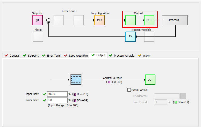
The Control Output range is 0 to 100% by default. But it can be changed by setting the Upper Limit (DFn+10) and Lower Limit (DFn+09).
If the Upper Limit is set to zero, the CO will never get above zero and the control loop will not function properly.
PWM (Pulse Width Modulated) control turns the Control Output signal into a series of pulses. The width of the pulse (or duty cycle) is the ratio of ON time to OFF time determined by the Control Output percentage of the Time Period.
Since PWM Control is determined by the type of output, it is enabled in the PID configuration; but unlike most other parameters, it is not modifiable by the Ladder Logic. No Address is assigned to the PWM Enable setting.
Bit Address: The address of the discrete output that is tied to the control element in the process. The programmer assigns this.
Time Period (DSn+07): The total of the ON and OFF time. This value can be 1 to 600 seconds.
The Raw Process Variable (DFn+11) is the measured value that the PID loop controls. It is directly affected by the process being controlled. The Process Variable (DFn+12) is the filtered Raw Process Variable used by the PID calculation. If the PV filter is not enabled, then the PV is equal to the Raw PV.
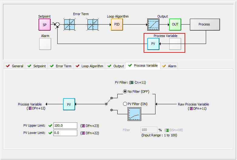
The PV Upper (DFn+23) and Lower (DFn+22) Limits are the expected process range values for the full range of the Control Output. They are used to calculate the Process gain which in turn is used by Autotune to calculate the Proportional Gain tuning constant.
This is not the range of the process measurement device or the PLC input configuration. For example the Input may be a RTD input with a range of -328 to 1562 Deg F. But the Process range for a CO of 0 to 100 may only be 40 to 140 Deg F. The PV Upper and Lower Limits would be 140 and 40 respectively.
Range: 1 - 100%
A noisy Raw PV can cause a PID loop to become unstable as well as make the loop difficult to tune. The CLICK PLC provides a PV Filter to reduce the high frequency noise in the Raw PV value to provide a clean PV to the PID Controller.
PV Filter(Cn+11): turns on the PV filter.
Filter Constant (DSn+8): the Filter Constant is the percentage of the Raw PV that is passed each PID sample time. The smaller the filter value, the more filtering that will occur. A value of 100 will result in no filtering and 100% of the Raw PV is passed The default value is 100.
|
|
Enabling the PV Filter and entering a small filter value can cause some lag in the PV. This should be taken into account while tuning. |
The CLICK PLC allows the user to specify alarm conditions that can be monitored for each loop. These alarms and alarm levels can be enabled and configured in the Alarm tab or though the PLC addresses. For more information on Alarms, see the Help topic PID Control in CLICK.
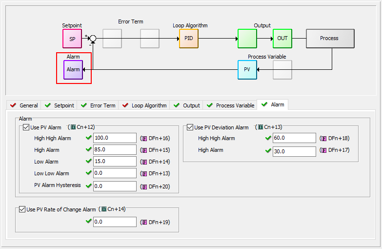
Use PV Alarm (Cn+12) - these are limit alarms. If the PV passes the limit, the corresponding C-bit is turned on.
Alarm Type
Alarm Limit
Alarm Status Bit
High-High Alarm
DFn+16
Cn+34
High Alarm
DFn+15
Cn+33
Low Alarm
DFn+14
Cn+32
Low-Low Alarm
DFn+13
Cn+31
Use PV Deviation Alarm (Cn+13): Sometimes the PV value is not a concern, but the difference between the PV and SP is a concern. You can specify a High Deviation Alarm or High High Deviation Alarm from the Setpoint. When the PV is further from the Setpoint than the programmed Deviation Limit, the corresponding C-bit is turned on. The deviation is the amount above or below the Setpoint.
Alarm Type
Alarm Limit
Alarm Status Bit
High-High Alarm
DFn+18
Cn+36
High Alarm
DFn+17
Cn+35
PV Alarm Hysteresis (DFn+20): The PV Limit Alarms and PV Deviation Alarms are programmed using limit values. When the PV value or deviation exceeds the configured limit, the alarm status bit becomes true. Real-world PV signals fluctuate. As the PV value crosses an alarm limit, its fluctuations will cause the alarm to be intermittent and trigger repeatedly.
The hysteresis is applied when the PV value passes a limit and descends back through it.
The alarm activates immediately when the Alarm limit is crossed. But the alarm delays turning off until the PV value has dropped below the limit by the hysteresis amount.
Use PV Rate of Change (Cn+14): When the PV changes faster than a specified rate-of-change limit (DFn+19). The Rate of Change C-bit (Cn+37) is set. The rate-of-change units are PV. Units change per sample time.
As an example, suppose the PV is the temperature for your process, and you want an alarm whenever the temperature changes faster than 15 degrees/minute. Suppose the sample rate is 2 seconds.

Related Topics: