|
|
Topic: P167 |
PID Loop (PID) Instruction |
|
|
|
Topic: P167 |
PID Loop (PID) Instruction |
|
Mnemonic (Keyboard Shortcut) = PID
Icon / Button =

A Proportional-Integral-Derivative algorithm is a generic Control Loop feedback formula widely used in industrial control systems. A PID algorithm attempts to correct the Error between a measured process variable and a desired setpoint by calculating and then outputting a corrective action that can adjust the process accordingly and rapidly, to keep the Error to a minimum.
|
Parameter |
Parameter Type |
Requirements |
Description |
|
Enable |
Boolean Ladder Rung Input |
A Ladder Rung with an Enable contact is required to execute. |
Level-driven. When Enable is ON, the instruction will operate every scan. When Enable is OFF, the instruction is not solved and its outputs are not updated. |
|
Manual/Auto |
Boolean Ladder Rung Input |
Must Have |
OFF is Manual Mode. ON is Auto Mode. In Manual Mode, PID calculations are made, but the Process Output is not updated. When the Process is ready to be controlled by the PID instruction, switch to Auto Mode. Initialization Mode settings determine how the loop handles the change-over. Note: It is expected that when the loop is in Manual Mode that an operator or other intelligent source is manually controlling the output by observing the PV and writing data to the output as necessary to keep the process under control. |
|
Configuration Tabs |
All the Parameters available to configure a PID Loop are broken down into Configuration Tabs. Each Tab provides Parameters to configure the PID Loop at different levels from a Basic PID Loop to more elaborate PID Loops. The following list shows the available Configuration Tabs and each is described below and linked for quick reference. Minor Tabs are only active when Cascade Mode is selected) |
||
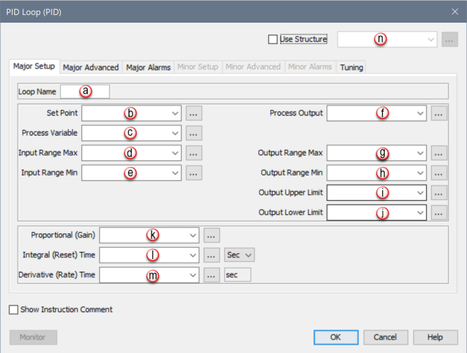
Major Setup Tab: Most parameters required to configure a basic PID Loop are located here.
|
Parameter |
Parameter Type |
Requirements |
Description |
|
Loop Name |
Constant |
Must Have |
Identifies this PID Loop. |
|
Set Point |
Numerical Tag |
Must Have |
The desired setting for the Process being controlled. |
|
Process Variable |
Numerical Tag |
Must Have |
A Feedback Signal that monitors the current state of the Process. |
|
Input Range Max |
Numerical Tag/ Constant |
Must Have |
The reference point that represents 100% in calculating the scaling factor to apply to the measured Error (SP-PV) before PID calculations. This value will not clamp the inputs. Typical value is the maximum possible input. See Note 1 below. |
|
Input Range Min |
Numerical Tag/ Constant |
Must Have |
The reference point that represents 0% in calculating the scaling factor to apply to the measured Error (SP-PV) before PID calculations. This value will not clamp the inputs. Typical value is the minimum possible input. See Note 1 below. |
|
Process Output |
Numerical Tag |
Must Have |
The result of the Loop Calculation, which drives the Process to the desired Set Point. |
|
Output Range Max |
Numerical Tag/ Constant |
Must Have if Analog out selected. |
The reference point that represents 100% in calculating the scaling factor to apply to the Process Output after PID calculations. This value will not clamp the Process Output. Typical value is the maximum possible Output. See Note 1 and Note 2 below. |
|
Output Range Min |
Numerical Tag/ Constant |
Must Have if Analog out selected. |
The reference point that represents 0% in calculating the scaling factor to apply to the Process Output after PID calculations. This value will not clamp the Process Output. Typical value is the minimum possible Output. See Note 1 below. |
|
Output Upper Limit |
Numerical Tag/ Constant |
Must Have |
Process Output will be clamped to no greater than this value. Typical value is the maximum possibleOutput. See Note 1 below. |
|
Output Lower Limit |
Numerical Tag/ Constant |
Must Have |
Process Output will be clamped to no less than this value. Typical value is the minimum possible Output. See Note 1 below. |
|
Proportional (Gain) |
Numerical Tag |
Must Have |
This value is directly Proportional to the control effect, meaning an increase to the Proportional value (sometimes referred to as Gain) will increase the control output for forward acting Loops and decrease the control output for reverse acting Loops. In the PID Algorithm, the Proportional Gain is multiplied by the Error during each sample and added to the Bias Term. Formula: Pgain * Error (SP-PV) Where: Pgain = Proportional Gain Error = The value difference between Process Variable (PV) and Setpoint (SP). SP = Set Point is the desired Setting for the controlled Process. PV = Process Variable is the Feedback Signal that monitors the current state of the Process. See Note 3 below. |
|
Integral (Reset) Time |
Numerical Tag |
Must Have |
This value is a Time constant that is used to remove Error after the control output has reached a steady state. The Integral Time setting isInverselyProportional to the control effect, meaning as the value increases, the rate at which the Error is removed decreases. In the PID Algorithm, the Integral Term is multiplied by the accumulated Error and added to the control output. Formula: CIT * ∑e Where: CIT = Coefficient of Integral Time ∑e = Summation of Error per sample Note: To minimize the effect of the Integral Term, give the tag assigned to it a very large initial value. Since the value is Inversely proportional to its effect on the calculation, this will effectively disable it. A zero in the Integral Term gives the maximum possible control effect. Also, See Note 3 below. |
|
Derivative (Rate) Time |
Numerical Tag |
Optional |
In many cases this parameter is not required to achieve stable Loop operation and is highly sensitive to noise in the Error Term. This value is directly Proportional to the control effect, meaning that the higher the Derivative Term setting, the quicker the Error will be removed. In the PID Algorithm, the Derivative Term formula is added to the control output. Formula: CDT *e + Initial Output Where: CDT = Coefficient of Derivative Time e = Current Error - Previous Error See Note 3 below. |
Note 1: This value will be read by the instruction only during an OFF to ON transition of the Enable.
Note 2: To see a change in the Process Output, a value greater than zero must be entered into this parameter.
Note 3: Using a Floating Point tag(s) for the P, I, & D fields allows tighter precision for maximum control.
When PID Loop Instruction is selected the PID Loop Configuration window shown below opens with the Major Setup Tab opened by default.
|
Parameter |
Parameter Type |
Requirements |
Description |
|
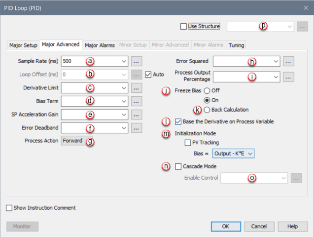
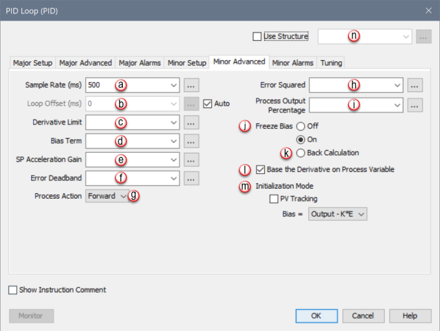
Sample Rate (ms) |
Numerical Tag/ Constant |
Must Have |
Identifies how often the instruction will calculate a new output value. Setting the Sample Rate shorter than the scan time will cause the loop to calculate on every scan. The sample rate must be longer than the rate at which new PV data is available. If it is not, the Integral and Derivative affects could be erratic. |
|
Error Squared |
Boolean Tag / Constant |
Optional |
Setting this bit will Square the Error. This can be useful for many processes by effectively diminishing the control effect on smaller Errors while maintaining the control effect on larger Errors. This can also be useful for reducing the effect of low frequency electrical noise in your process. |
|
Loop Offset (ms) |
Numerical Tag/ Constant |
Must Have if Auto Mode is not selected |
When set to Auto Mode, the CPU attempts to stagger the execution of PID Loops so they will occur on different scans. Loop Offset can be handled manually by assigning different Offset values to multiple PID Loops. |
|
Process Output Percentage |
Numerical Tag |
Optional |
The current Output Percentage on a scale of 0-100%. |
|
Derivative Limit |
Numerical Tag/ Constant |
Optional |
Multiplier that limits the Output adjustment applied by the Derivative term. 1 = 100% of Output scale, or No Limit (default). 0.5 = 50% of Output scale. |
|
Bias Term |
Numerical Tag |
Optional |
The Bias Term is the Current Integral Term + Initial Output. The Bias Term is a value calculated by the instruction, which effectively creates a working region for the Control Output. |
|
Freeze Bias |
Radio Button |
Optional |
Default Setting in ON. Stops the Bias Term calculation when the Output value reaches the upper or lower limit (usually due to a disturbance). This setting prevents reset wind-up which can lead to overshooting the Set Point when a disturbance is removed. |
|
Back Calculation |
Radio Button |
Optional |
If the Output is calculated to be above or below the upper or lower limit, this option will adjust the Bias Term accordingly to make the Output equal to the limit. As soon as the process begins to recover, the loop will go directly into regulation. This anti-windup option is more conservative than Freeze Bias, typically less likely to overshoot but slower to recover from the disturbance. |
|
Base the Derivative on Process Variable |
Selectable Checkbox |
Optional |
When selected, the Derivative is based on changes in the Process Variable. When deselected the Derivative is based on changes in the Error term (SP – PV). |
|
SP Accel Gain |
Numerical Tag/ Constant |
Optional |
A value of 0 disables this function. The process monitors for a change in the set point value. If a set point change is detected, the difference from the new and old set points are multiplied by the SP Accel Gain value and then added to the Bias Term. This action is Edge triggered so it processes only once per change in the set point value. |
|
Error Deadband |
Numerical Tag |
Optional |
When used, the Error Deadband takes a range of Error and substitutes Zero as the value of the Error. Enter the value in Input Units. |
|
Initialization Mode |
Selectable Drop-down List |
Check the PV Tracking checkbox or Select one from the list |
Determine the state of the Process Variable and Bias Term at startup.
|
|
Process Action |
Selectable Drop-down List |
Select one from the list |
Determines how the Process reacts to the Output. The two choices are:
|
|
Cascade Mode |
Selectable Checkbox |
Click on the checkbox to activate Cascade Mode |
When selected, Enables the Minor Loop configuration tabs within the PID Loop instruction setup. The first Loop is commonly referred to as the Major Loop or Outer Loop and the Second Loop is commonly referred to as the Minor Loop or Inner Loop. (See Cascade Mode later on in this section). |
|
Enable Control |
Boolean Tag |
Optional |
Level Driven. When this Tag is ON the Output of the Major Loop is redirected as the set point signal of the Minor Loop. When this Tag is OFF, the Minor Loop functions independently and uses the Auto Mode SP Tag as the set point. The ladder Input Manual/Auto must be ON when Enable Control is turned ON. Enable Control will have no effect if Manual/Auto is OFF. (See Note 1 below) |
Note 1: When enabling cascade control, a minimum delay of 1 second must be added after enabling the PID loop.
When PID Loop Instruction is selected the PID Loop Configuration window opens with the Major Setup Tab opened by default. Click on the Major Advanced Tab to see the Configuration options for Major Advanced shown below.
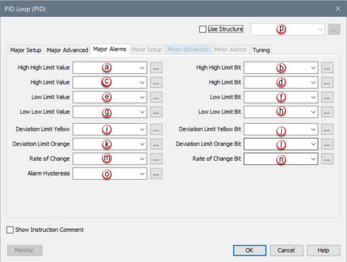
This Tab provides Configuration for Major PID Alarm condition Tags.
|
Parameter |
Parameter Type |
Requirements |
Description |
|
High High Limit Value |
Numerical Tag/ Constant |
Optional |
If used, when the Process Variable is Greater Than or Equal To this value, the High High Limit Bit will turn ON. |
|
High High Limit Bit |
Boolean Tag |
Optional |
Turns ON if the Process Variable signal is Greater Than or Equal To the High High Limit parameter setting. |
|
High Limit Value |
Numerical Tag/ Constant |
Optional |
If used, when the Process Variable is Greater Than or Equal To this value, the High Limit Bit will turn ON. |
|
High Limit Bit |
Boolean Tag |
Optional |
Turns ON if the Process Variable signal is Greater Than or Equal To the High Limit parameter setting. |
|
Low Limit Value |
Numerical Tag/ Constant |
Optional |
If used, when the Process Variable is Less Than or Equal To this value, the Low Limit Bit will turn ON. |
|
Low Limit Bit |
Boolean Tag |
Optional |
Turns ON if the Process Variable signal is Less Than orEqual To the Low Limit parameter setting. |
|
Low Low Limit Value |
Numerical Tag/ Constant |
Optional |
If used, when the Process Variable is Less Than or Equal To this value, the Low Low Limit Bit will turn ON. |
|
Low Low Limit Bit |
Boolean Tag |
Optional |
Turns ON if the Process Variable signal is Less Than or Equal To the Low Low Limit parameter setting. |
|
Deviation Limit Yellow |
Numerical Tag/ Constant |
Optional |
One of two user definable Alarms that show when the Error is out of a specified range. The value specified is reflected as the range above AND below the Set Point. If used, when the Error reaches this value, the Deviation Limit Yellow Bit will turn ON. |
|
Deviation Limit Yellow Bit |
Boolean Tag |
Optional |
Turns ON if the Deviation Limit Yellow is reached. |
|
Deviation Limit Orange |
Numerical Tag/ Constant |
Optional |
One of two user definable Alarms that show when the Error is out of a specified range. The value specified is reflected as the range above AND below the Set Point. If used, when the Error reaches this value, the Deviation Limit Orange Bit will turn ON. |
|
Deviation Limit Orange Bit |
Boolean Tag |
Optional |
Turns ON if the Deviation Limit Orange is reached. |
|
Rate of Change |
Numerical Tag/ Constant |
Optional |
When used, if the Process Variable Changes at a Rate greater than this value (in Input Units per Second), the Rate of Change Bit will turn ON. |
|
Rate of Change Bit |
Boolean Tag |
Optional |
Turns ON if the Rate of Change Setting is reached. |
|
Alarm Hysteresis |
Numerical Tag/ Constant |
Optional |
Allows the user to specify a Numeric value that will offset the OFF transition of your process Alarms. The Alarm Bits will transition ON at the user defined value, but will add the Hysteresis value before it transitions OFF. This helps prevent cycling of the Alarm Bit as a noisy PV bounces in and out of the Alarm range.
|
When PID Loop Instruction is selected the PID Loop Configuration window opens with the Major Setup Tab opened by default. Click on the Major Alarms Tab to see the Configuration options for Major Alarms shown below.
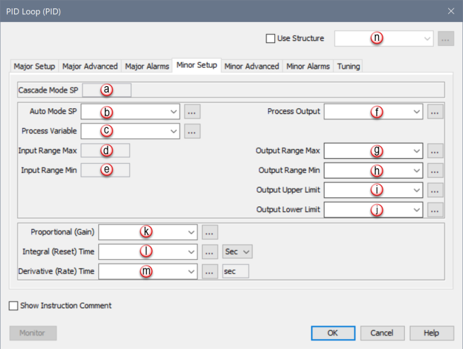
This Tab is only active when the Cascade Mode selection found in the Major Advanced Tab is selected. This Tab provides all the Main Configuration parameters for the Cascaded Loop.
|
Parameter |
Parameter Type |
Requirements |
Description |
|
Cascade Mode SP |
Numerical Tag/ |
Must Have |
The Set Point (SP) generated by the Major Loop Control Output when Cascade mode Control is Enabled. |
|
Auto Mode SP |
Numerical Tag/ Constant |
Must Have |
The Minor Loop Set Point when Cascade Mode Control is not Enabled. |
|
Process Variable |
Numerical Tag/ Constant |
Must Have |
A Feedback Signal that monitors the current state of the Process. |
|
Input Range Max |
Numerical Tag/ Constant |
Must Have |
The reference point that represents 100% in calculating the scaling factor to apply to the measured Error (SP-PV) before PID calculations. This value will not clamp the inputs. Typical value is the maximum possible input. See Note 1 below |
|
Input Range Min |
Numerical Tag/ Constant |
Must Have |
The reference point that represents 0% in calculating the scaling factor to apply to the measured Error (SP-PV) before PID calculations. This value will not clamp the inputs. Typical value is the minimum possible input. See Note 1 below |
|
Process Output |
Numerical Tag |
Must Have |
The result of the Loop Calculation, which drives the Process to the desired Set Point. |
|
Output Range Max |
Numerical Tag/ Constant |
Must Have if Analog out selected. |
The reference point that represents 100% in calculating the scaling factor to apply to the Process Output after PID calculations. This value will not clamp the Process Output. Typical value is the maximum possible Output. See Note 1 and Note 2 below |
|
Output Range Min |
Numerical Tag/ Constant |
Must Have if Analog out selected. |
The reference point that represents 0% in calculating the scaling factor to apply to the Process Output after PID calculations. This value will not clamp the Process Output. Typical value is the minimum possible Output. See Note 1 below |
|
Output Upper Limit |
Numerical Tag/ Constant |
Must Have |
Process Output will be clamped to no greater than this value. Typical value is the maximum possible Output. |
|
Output Lower Limit |
Constant |
Must Have |
Process Output will be clamped to no less than this value. Typical value is the minimum possible Output. |
|
Proportional (Gain) |
Numerical Tag |
Must Have |
This value is directly Proportional to the control effect, meaning an increase to the Proportional value (sometimes referred to as Gain) will increase the control output for forward acting Loops and decrease the control output for reverse acting Loops. In the PID Algorithm, the Proportional Gain is multiplied by the Error during each sample and added to the Bias Term. Formula: Pgain * Error (SP-PV) Where: Pgain = Proportional Gain Error = The value difference between Process Variable (PV) and Setpoint (SP). SP = Set Point is the desired Setting for the controlled Process. PV = Process Variable is the Feedback Signal that monitors the current state of the Process. |
|
Integral (Reset) Time |
Numerical Tag |
Must Have |
This value is a Time constant that is used to remove Error after the control output has reached a steady state. The Integral Time setting is inversely Proportional to the control effect, meaning as the value increases, the rate at which the Error is removed decreases. In the PID Algorithm, the Integral Term is multiplied by the accumulated Error and added to the control output. Formula: C IT
Where: CIT = Coefficient of Integral Time ∑e = Summation of Error per sample |
|
Derivative (Rate) Time |
Numerical Tag |
Optional |
In many cases this parameter is not required to achieve stable Loop operation and is highly sensitive to noise in the Error Term. This value is directly Proportional to the control effect, meaning that the higher the Derivative Term setting, the quicker the Error will be removed. In the PID Algorithm, the Derivative Term formula is added to the control output. Formula: CDT * e + Initial Output Where: CDT = Coefficient of Derivative Time e = Current Error - Previous Error |
Note 1: This value will be read by the instruction only during an OFF to ON transition of the Enable.
Note 2: To see a change in the Process Output, a value greater than zero must be entered into this parameter.
When PID Loop Instruction is selected, the PID Loop Configuration window opens with the Major Setup Tab opened by default. This Tab is only active when the Cascade Mode selection found in the Major Advanced Tab is selected. Therefore, select Cascade Mode first and then click on the Minor Setup Tab to see the Configuration options for Minor Setup shown below.
This Tab is only active when the Cascade Mode selection found in the Major Advanced Tab is selected. The Minor Advanced Tab provides all the Advanced Configuration parameters for the Cascaded Loop.
|
Parameter |
Parameter Type |
Requirements |
Description |
|
Sample Rate (ms) |
Numerical Tag/ Constant |
Must Have |
Identifies how often the instruction will calculate a new output value. Setting the Sample Rate shorter than the scan time will cause the loop to calculate on every scan. The sample rate must be longer than the rate at which new PV data is available. If it is not, the Integral and Derivative affects could be erratic. |
|
Error Squared |
Boolean Tag/ Constant |
Optional |
Setting this bit will Square the Error. This can be useful for many processes by effectively diminishing the control effect on smaller Errors while maintaining the control effect on larger Errors. This can also be useful for reducing the effect of low frequency electrical noise in your process. |
|
Loop Offset (ms) |
Numerical Tag/ Constant |
Must Have if Auto Mode is not selected |
When set to Auto Mode, the CPU attempts to stagger the execution of PID Loops so they will occur on different scans. Loop Offset can be handled manually by assigning different Offset values to multiple PID Loops. |
|
Process Output Percentage |
Numerical Tag |
Optional |
The current Output Percentage on a scale of 0-100%. |
|
Derivative Limit |
Numerical Tag/ Constant |
Optional |
Multiplier that limits the Output adjustment applied by the Derivative term. 1 = 100% of Output scale, or No Limit (default). 0.5 = 50% of Output scale. |
|
Bias Term |
Numerical Tag |
Optional |
The Bias Term is the Current Integral Term + Initial Output. The Bias Term is a percentage value calculated by the instruction, which effectively creates a working region for the Control Output. |
|
Freeze Bias |
Radio Button |
Optional |
Default Setting is ON. Stops the Bias Term calculation when the Output value reaches the upper or lower limit (usually due to a disturbance). This setting prevents reset wind-up which can lead to overshooting the Set Point when a disturbance is removed. |
|
Back Calculation |
Radio Button |
Optional |
If the Output is calculated to be above or below the upper or lower limit, this option will adjust the Bias Term accordingly to make the Output equal to the limit. As soon as the process begins to recover, the loop will go directly into regulation. This anti-windup option is more conservative than Freeze Bias, typically less likely to overshoot but slower to recover from the disturbance. |
|
Base the Derivative on Process Variable |
Selectable Checkbox |
Optional |
When selected, uses the Derivative is based on changes in the Process Variable. When deselected the Derivative is based on changes in the Error term (SP – PV). |
|
SP Accel Gain |
Numerical Tag/ Constant |
Optional |
A value of 0 disables this function. The process monitors for a change in the set point value. If a set point change is detected, the difference from the new and old set points are multiplied by the SP Accel Gain value and then added to the Bias Term. This action is Edge triggered so it processes only once per change in the set point value. |
|
Error Deadband |
Numerical Tag |
Optional |
When used, the Error Deadband takes a range of Error near Zero and substitutes Zero as the value of the Error. Enter the value in Input Units. |
|
Initialization Mode |
Selectable Drop-down List |
Check the PV Tracking checkbox or Select one from the list |
Determine the state of the Process Variable and Bias Term at startup.
|
|
Process Action |
Selectable Drop-down List |
Select one from the list |
Determines how the Process reacts to the Output. The two choices are:
|
When PID Loop Instruction is selected the PID Loop Configuration window opens with the Major Setup Tab opened by default. This Tab is only active when the Cascade Mode selection found in the Major Advanced Tab is selected. Therefore, select Cascade Mode first and then click on the Minor Advanced Tab to see the Configuration options for Minor Advanced shown below.
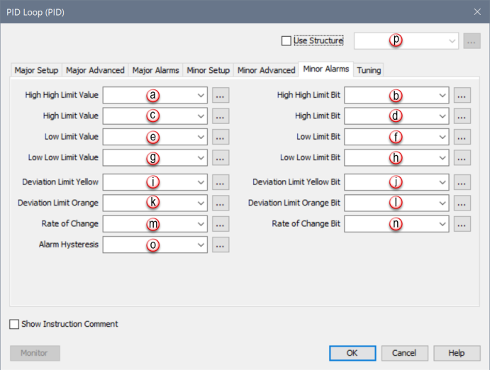
This Tab is only active when the Cascade Mode selection found in the Major Advanced Tab is selected. This Tab provides all the Minor Alarms Configuration parameters for the Cascaded Loop.
|
Parameter |
Parameter Type |
Requirements |
Description |
|
High High Limit Value |
Numerical Tag/ Constant |
Optional |
If used, when the Process Variable is Equal To or Greater Than this value, the High High Limit Bit will turn ON. |
|
High High Limit Bit |
Boolean Tag |
Optional |
Turns ON if the Process Variable signal is Equal To or Greater Than the High High Limit parameter setting. |
|
High Limit Value |
Constant |
Optional |
If used, when the Process Variable is Equal To or Greater Than this value, the High Limit Bit will turn ON. |
|
High Limit Bit |
Boolean Tag |
Optional |
Turns ON if the Process Variable signal is Equal To or Greater Than the High Limit parameter setting. |
|
Low Limit Value |
Numerical Tag/ Constant |
Optional |
If used, when the Process Variable is Less Than or Equal To this value, the Low Limit Bit will turn ON. |
|
Low Limit Bit |
Boolean Tag |
Optional |
Turns ON if the Process Variable signal is Less Than or Equal To the Low Limit parameter setting. |
|
Low Low Limit Value |
Numerical Tag/ Constant |
Optional |
If used, when the Process Variableis Less Than or Equal To this value, the Low Low Limit Bit will turn ON. |
|
Low Low Limit Bit |
Boolean Tag |
Optional |
Turns ON if the Process Variable signal is Less Than or Equal To the Low Low Limit parameter setting. |
|
Deviation Limit Yellow |
Numerical Tag/ Constant |
Optional |
One of two user definable Alarms that show when the Error is out of a specified range. The value specified is reflected as the range above AND below the Set Point. If used, when the Error reaches this value, the Deviation Limit Yellow Bit will turn ON. |
|
Deviation Limit Yellow Bit |
Boolean Tag |
Optional |
Turns ON if the Deviation Limit Yellow is reached. |
|
Deviation Limit Orange |
Numerical Tag/ Constant |
Optional |
One of two user definable Alarms that show when the Error is out of a specified range. The value specified is reflected as the range above AND below the Set Point. If used, when the Error reaches this value, the Deviation Limit Orange Bit will turn ON. |
|
Deviation Limit Orange Bit |
Boolean Tag |
Optional |
Turns ON if the Deviation Limit Orange is reached. |
|
Rate of Change |
Numerical Tag/ Constant |
Optional |
When used, if the Process Variable Changes at a Rate greater than this value (in Input Units per Second), the Rate of Change Bit will turn ON. |
|
Rate of Change Bit |
Boolean Tag |
Optional |
Turns ON if the Rate of Change Setting is reached. |
|
Alarm Hysteresis |
Numerical Tag/ Constant |
Optional |
Allows the user to specify a Numeric value that will offset the OFF transition of your process Alarms. The Alarm Bits will transition ON at the user defined value, but will add the Hysteresis value before it transitions OFF. This helps prevent cycling of the Alarm Bit as a noisy PV bounces in and out of the Alarm range.
|
When PID Loop Instruction is selected the PID Loop Configuration window opens with the Major Setup Tab opened by default. The Minor Alarms Tab is only active when the Cascade Mode selection found in the Major Advanced Tab is selected. Therefore, select Cascade Mode first and then click on the Minor Alarms Tab to see the Configuration options for Minor Alarms shown below.
You can use External Auto Tune to start and stop an auto-tuning session through an external HMI/SCADA. For a description of the Auto Tune process, please refer to Auto Tune Settings under PID Tuning.
Configure the External Auto Tune control/status parameters using the Tuning Tab located on the PID Loop (PID) screen.
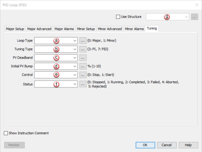
0: Stopped External Auto Tune is stopped/disabled 1: Running External Auto Tune is currently running 2: Completed External Auto Tune has completed successfully 3: Failed External Auto Tune has failed 4: Aborted External Auto Tune was aborted by user 5: Rejected External Auto Tune was rejected
The letters PID refer to Proportional, Integral, Derivative control. PID is a Control Algorithm used to closely control processes such as temperature, mixture, position, and velocity. The Proportional Gain portion takes care of the magnitude of the Error and is calculated using terms of percent of full scale, not counts or engineering units. The Integral takes care of small Errors over time. The Derivative compensates for the Rate of Error change.
Consider this example application. For simplification, only Proportional Gain is used. An oven is being controlled by an SCR-driven electric heater using a 4-20mA Output channel. This Analog Output is the Process Output. The temperature of the oven is measured using an RTD via a P3-08RTD module. This Input is the Process Variable (PV). The desired temperature of the oven is the Set Point (SP).
For Input values such as Set Point (SP) and Process Variable (PV), full scale is the span between Input Range Min and Input Range Max of the PID instruction. In this example, the P3-08RTD provides temperature in degrees directly, not counts, where every four degrees is 1% of full scale.
If the Set Point is 300 and the Process Value (RTD) is 292, the Error would be 8 degrees. With the scaling set by Input Range Min and Input Range Max, 8 degrees Error represents 2% of the Input range. The2% is multiplied by Proportional Gain. If the Proportional Gain is 10, the result would be 2%*10=20%. So with these variables applied, Proportional Gain alone would drive the Process Output to 20% of full scale, with full scale being defined by the Output Range Max and Output Range Min tags.
The SCR controlling the heater is driven by a 4-20mA Analog Output point accepting values of 0-65535. Output Range Min and Output Range Max might be set to 0 and 65535 respectively. In the above example, with the Error being 8 degrees, the Output would be driven to 20% of full scale or 13107 counts, sending 7.2mA to the SCR.
Note: If the Proportional Gain is set too Low, the PID Control will be slow and ineffective in driving the Output to correct for Errors between the Process and Set Point. If set too High, the PID will produce oscillations as the Process Variable approaches the Set Point.
Integral Time: Unless the process naturally has the correct Integrating Properties, some Offset will result between the Process Variable and SetPoint. The Integral Gain will correct or reset this Error or Offset.
The CPU uses 1/Ts (the sample rate), which produces a reciprocal effect, meaning the larger the number the less effect the Integral Gain will have.
Note: After the Proportional Gain is set, if the Integral Gain is set too Low (too large of a value), then the PID control will be ineffective correcting Process Variable and Set PointOffsets. If set too High (too small a value), then the Process Variable will overshoot the Set Point and oscillations will occur.
Derivative (Rate):Proportional Gain and Integral Gain can handle many processes. However, when large disturbances are introduced into the process, this creates sudden and large errors between the Process Variable and Set Point. The Derivative value will react to these sudden disturbances and attempt to correct the error while maintaining the stability of the loop.
Note: The larger the number, the more effective the Rate will respond to Process Upsets. However, the Rate should be set just high enough to help the effects of Process Upsets. If the Rate is set too High, the Proportional and Integral Gain normal action will be adversely effected and the Proportional and Integral Gain control will become sluggish and ineffective.
The Proportional Integral Derivative (PID)Algorithm is widely used in process control. The PID method of control adapts well to electronic solutions, whether implemented in analog or digital (CPU) components. The CPU implements the PID equations digitally by solving the basic equations in software. I/O modules serve only to convert electronic signals into digital form (or vice versa).
The PID Algorithm causes the PID equation to calculate the Control OutputMn:
In the formula below, the sum of the Integral Terms and the Initial Output are combined into the Bias Term (Mx). Using the Bias Term, we define formulas for the Bias and Control Output as a function of sampling time:
Detailed analysis of these equations will be found in most good textbooks on Process Control. At a glance, we can isolate the parts of the PID Algorithm that correspond to the P, I, and D terms, and the Bias as shown below.
The Initial Output is the Output value assumed from Manual Mode control when the Loop transitions to Auto Mode. The sum of the Initial Output and the Integral Term is the Bias Term, which holds the Position of the Output.
In this example, we will apply the PID algorithm to a temperature control loop. The loop is maintaining the temperature of an oven. The desired temperature of the oven is 350˚F. For this loop, we will set the algorithm’s parameters as follows:
Looking at the graph below, we can see that with this control output the loop has been stable at 350˚F for the first five samples.
After the fifth sample, the oven door is opened and an item is placed inside. This causes a drop of 20˚F in our actual temperature which is seen at sample six. Therefore, the error in the system at sample six is calculated to be: e(6) = SP-PV = 350 - 330 = 20. Also, at this point the sum of all the sample errors for the system will equal:

Using the parameters and calculated values above, the algorithm for the loop at sample six would become:
M(6) = (3*20)+(0.1*20)+(0*(20-0))+30
M(6) = 60 + 2 + 30
M(6) = 92 - At this point, there is an increase in the control output of 62 from the initial control output and the proportional term is the main force driving this increase with a value of 60.
As discussed in the What is PID? section of this chapter, the control output will be converted to an analog value (0-10V, 4-20mA) that is fed to an end device. In our example, that device is an SCR-driven electric heater. As the control output drives the temperature toward the setpoint, we see at sample seven that the error has decreased to: e(7) = SP-PV = 350 - 340 = 10. Also at this point, the sum of all the sample errors will equal 30 and the algorithm will become:
M(7) = (3*10)+(0.1*30)+(0*(10-20))+30
M(7) = 30 + 3 + 30
M(7) = 63 - Here we see that as the error is corrected, the control output will decrease due to the drop in the proportional term. However, the integral term has risen slightly.
At sample eight, the oven temperature has recovered to 349.5˚F leaving a minimal error of: e(8) = SP-PV = 350 - 349.5 = 0.5. The sum of all sample errors is now 30.5 and the control output equals:
M(8) = (3*0.5)+(0.1*30.5)+(0*(0.5-10))+30
M(8) = 1.5 + 3.05 + 30
M(8) = 34.55 - At this point, the proportional term has dropped off considerably and the integral bias has exceeded the proportional gain in controlling the output.
When tuning a loop, it is important to remember that with large errors the proportional term will drive the output and with small errors the integral term will take control.
The last item to consider when dealing with a PID controlled system is the rate of change in the process variable. With our example, the rate of change is very rapid when the door is opened. A 20˚F drop within one second. With very rapid changes, there is a risk of instability in the loop and the derivative term attempts to alleviate this while aiding in the correction. The derivative term will look at the difference between the error now and the error before, determine how rapidly the process variable is deviating from or correcting to the setpoint and adjust the output accordingly. If we add a derivative coefficient of Kr = 0.5 (set the Derivative Time (Td) to 0.167 seconds, Kr = 3*0.167/1 = 0.5) to the samples in our discussion they become:
M(6) = (3*20)+(0.1*20)+(0.5*(20-0))+30
M(6) = 60 + 2 + 10 + 30
M(6) = 102
M(7) = (3*10)+(0.1*30)+(0.5*(10-20))+30
M(7) = 30 + 3 - 5 + 30
M(7) = 58
M(8) = (3*0.5)+(0.1*30.5)+(0.5*(0.5-10))+30
M(8) = 1.5 + 3.05 - 4.75 + 30
M(8) = 29.8
Looking at sample eight (M(8)) and disregarding the initial output (M(0)), we can see that with the derivative influence the bias applied to the control output dropped from 4.55 to -0.2. The derivative term determined that the process variable was approaching the setpoint at a very rapid rate and dampened the control output to avoid an overshoot of the setpoint.
Cascade PID Loop Control can improve your system performance when compared to a Single Loop Control if your process demonstrates one of the following characteristics:
- In this case a Cascade Controlled System can limit the effects of disturbances on the second process variable on the primary output.
- In this case a Cascade Controlled System can limit the effect of variations in the secondary system on the main control system's performance.
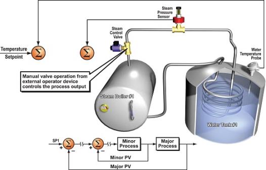
There are three modes of operation to consider when operating a Cascade Loop process:
- In Manual Mode the algorithm is not calculated and the user can write values to the Process Output variable (Steam Control Valve) as shown in the diagram below.
- Set Point and Process Variables are updated but not acted upon.
- Alarms are active in Manual Mode.
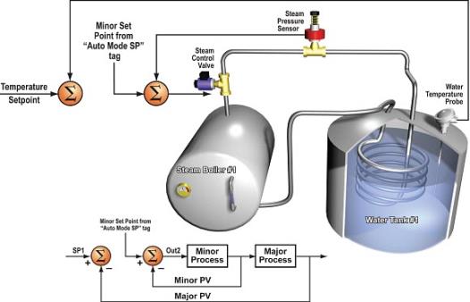
- In Auto Mode both the Major andMinor Loopsare calculated as individual Loops. The Minor Loop set point is pulled from theAuto Mode SP Tag defined in theMinor Setup Tabof the instruction and not from theMajor Loops Output, as shown in the diagram below.
- Set Point and Process Variables are updated but not acted upon.
- Alarms are active in Auto Mode.
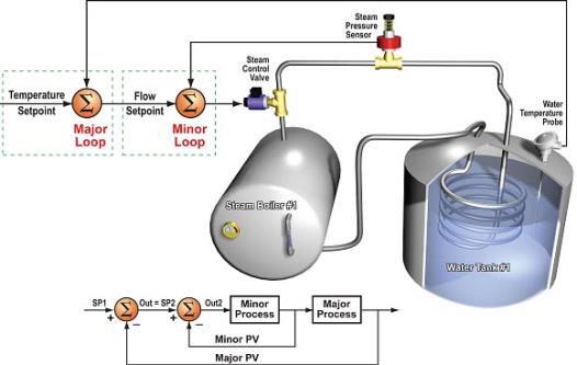
- In Cascade Mode both the Major and Minor Loops are calculated as a CombinedLoop. The Minor Loop set point is pulled from the Major Loop's Output as shown in the diagram below.
The PID Loop Control Output signal generates a smooth signal across a numerical range. The Control Output value is suitable to drive an Analog Output Module, which connects to the process. In the process control field, this is called continuous Control, because the output is on (at some level) continuously.
While continuous Control can be smooth and robust, the cost of the Loop components (such as actuators, heater amplifiers) can be expensive. A simpler form of Control is called time-proportioning Control or ON/OFF Control. This method uses actuators that are either ON or OFF (no in-between). Loop components for ON/OFF-Based Control systems are lower cost than their continuous Control counterparts.
The diagram below shows a hot-air balloon following a path across some mountains. The desired path is the Setpoint. The balloon pilot turns the burner ON and OFF alternately, which is his Control Output. The large mass of air in the balloon effectively averages the effect of the burner, converting the bursts of heat into a continuous effect: slowly hanging balloon temperature and ultimately the altitude, which is the Process Variable.

Time-Proportioning Control approximates continuous Control by virtue of its duty-cycle – the ratio of ON time to OFF time. The following figure shows an example of how duty cycle approximates a continuous level when it is averaged by a large process mass.
The example logic below shows how you would convert the smooth continuous Control signal from the PID Control Output to a pulsing Time-Proportioning Control for applications that require it.
The example logic below shows how you would convert the smooth continuous Control signal from the PID Control Output to a Pulsing Time-Proportioning Control for applications that require it.
The example program uses two timers to generate ON/OFF Control. It makes the following Assumptions, which you can alter to fit your application:
The Control program must Match the resolution of the Output to the resolution of the Time Interval. The Time Interval for one full cycle of the ON/OFF waveform is 10 seconds.
Note: Some processes change too fast for Time Proportioning Control. Consider the speed of your process when you choose this Control method. Use continuous Control for processes that change too fast for Time Proportioning Control.