Using XMC to Create an XYZ Gantry Robot
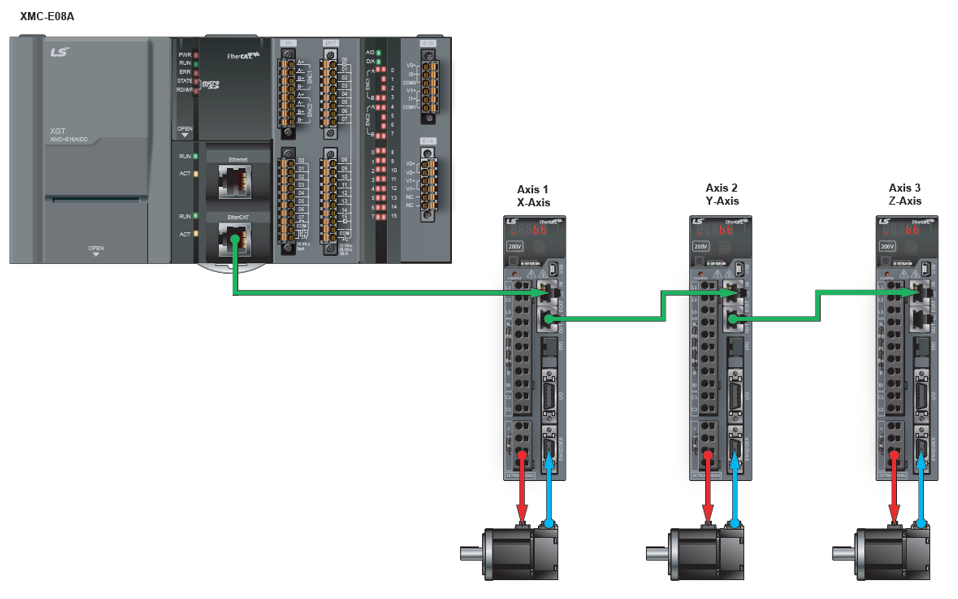
The LS Electric XMC programmable motion controller provides advanced functionality to control various types of robots such as XYZ gantry, Delta3, Delta 3R, Linear Delta, and others. This tutorial will show a quick setup of an XYZ gantry robot using an XMC-E08A and 3 LS Electric iX7HN servo drives.
-
A gantry can be designed on our website at https://www.automationdirect.com/selectors/xyzgantry.
-
igus drylin series ZLW linear belt actuators are being used for this example.
| Name/Acronym | Decription |
|---|---|
| ACS | Axes Coordinate System: The system of coordinates related to the physical motors and the single movements caused by the single drives. |
| Blending | A way that consecutive function blocks cooperate in the transition from the first to the next. |
| Contour curve | Inserted curve that modifies the original path. It is the resulting curve after blending. |
| Coordinate system | The reference system in which a coordinate or path is described. |
| Corner deviation | The shortest distance between the programmed corner point and the contour curve. |
| Corner distance | Distance of the start point of the contour curve to the programmed target point. |
| Direction | The orientational components of a vector in space. |
| Group-FB | The set of function blocks that can work on a group of axes. |
| MCS |
Machine Coordinate System - the system of coordinates that is related to the machine. A Cartesian coordinate system with the origin in a fixed position relative to the machine (the origin is defined during the machine setup). Sometimes called “World Coordinate System” or “Base Coordinate System”. Note: With Cartesian build machines, MCS is a Cartesian Coordinate system and may be identical to ACS, or mapped via a trivial transformation. The coordinate system from the physical multiple axes ACS is linked to the MCS via a kinematic transformation (forward and backward conversion). The MCS represents an imaginable space with up to 6 dimensions. |
| Orientation | The rotational components of a vector in space. |
| Path | Set of continuous positions and orientation information in multi-dimensional space Geometrical description of a space curve that the TCP of an axesgroup moves along. |
| PathData | Description of a path which can include additional information like velocity and acceleration. |
| PCS |
The coordinate system of the product can be called PCS – Product Coordinate System (or “Program Coordinate System” in CNC world, or Programmers Coordinate System). The PCS is based on the MCS typically by shifting and maybe rotating the MCS. The Zero point of the PCS is related to the product and can be changed during runtime by the program. The real work piece can have a rotation or shift to the MCS coordinate system or even might be moving relative to the MCS coordinate system. By specifying a trajectory in PCS one is able to describe the trajectory independent from the machine situation. To map these two worlds (MCS to PCS and vice versa), a cartesian or cylindrical transformation is normally done. |
| Position |
Position means a point in space which is described by different coordinates. Depending on the used system and transformation it can consist of up to 6 dimensions (coordinates) meaning 3 Cartesian coordinates in space and 3 coordinates for the orientation. In ACS there can be even more than 6 coordinates. If the same position is described in different coordinate systems the values of the coordinates are different. |
| Synchronization | Combines an axis or axes group (as slave) with an axis as master in order that the slave executes its path with synchronization to the progress of the master, meaning linked to a one- dimension source for synchronization. |
| TCP | Tool Center point, the point in the machine that is commanded to move, typically the center or the head of the tool. It can be described in different coordinate systems. |
| Tracking | Is characterized by an axis group that follows with its movement the movement of another axis group. |
| Trajectory |
Time dependent description of the path the TCP of an axes group moves along. Additionally to the geometrical description of the space curve, time dependent state variables like velocity, acceleration, jerk, forces etc. are specified. |
| Velocity |
For a group of axes this means:
|
Axis Group Command Function Blocks will be used to setup the gantry and command movements.
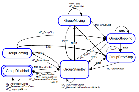
Note: See Group PLCopen state machine for more information on group behavior.
| Axis Group Command | Description of Functionality |
|---|---|
| MC_AddAxisToGroup | Add one axis to a motion group. Note: Axes can be added to a group in the Axis Group Parameters as well. |
| MC_RemoveAxisFromGroup | Removes one axis from a group. |
| MC_UngroupAllAxes | Removes all axes from a group. |
| MC_GroupEnable | Changes the state for a group from GroupDisabled to GroupStandby. |
| MC_GroupDisable | Changes state for a group to GroupDisabled. |
| MC_GroupPower | Servo on/off for all axes in the group. |
| MC_GroupHome | Commands the group to perform their homing procedure. |
| MC_GroupSetPosition | Sets the position of all axes in the group without moving. |
| MC_GroupStop | Stop a group’s movement immediately. |
| MC_GroupHalt | Stop a group’s movement. |
| MC_GroupReset | Reset a group error. |
| MC_MoveLinearAbsolute | Absolute positioning linear interpolation operation. |
| MC_MoveLinearRelative | Relative positioning linear interpolation operation. |
| MC_MoveCircularAbsolute | Absolute positioning circular interpolation operation |
| MC_MoveCircularRelative | Relative positioning circular interpolation operation |
| MC_SetCartesianTransform | Sets a Cartesian transformation between the MCS and PCS. |
| MC_GroupSetOverride | Overrides the velocity, acceleration, and jerk values of an axis group movement. |
| LS_ReadGroupParameter | Read parameters of an axis group. |
| LS_WriteGroupParameter | Write parameters of an axis group. |
The Group State diagram reflects the state of the group and all the issued function blocks.
Notes:
-
Applicable for all non-administrative (moving) function blocks.
-
In the states GroupErrorStop or GrouptStopping, all function blocks can be called, although they will not be executed, except MC_GroupReset for GroupErrorStop and any occuring error--they will generate the transition to GroupStandby or GroupErrorStop respectively.
-
MC_GroupStop.DONE AND NOT MC_GroupStop.EXECUTE
-
Transition is applicable if last axis is removed from the group
-
Transition is applicable while group is not empty
-
MC_GroupDisable and MC_UngroupAllAxes can be issued in all states and will change the state to GroupDisabled
-
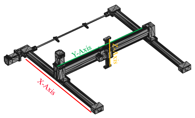
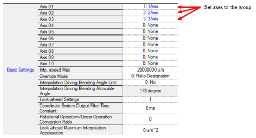
X-Axis (Axis 1): Movement range of 600 mm and Pitch is 70 mm.
-
Y-Axis (Axis 2): Movement range of 600 mm and Pitch is 70 mm.
-
Z-Axis (Axis 3): Movement range of 150 mm and Pitch is 70 mm.
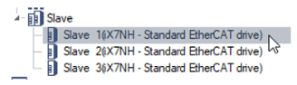
Slave homing mode can be configured from the SDO data of the slave. See How to Review and Edit the EtherCAT Service Data Object (SDO) for more information on modifying and writing SDO data from the XMC. Homing Method 28 will be selected for all three axes for this example. This homing method will search for the Home switch in the reverse direction. Write the SDO configuration to the slaves to make sure the homing method is updated.
| Step | Action |
|---|---|
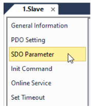
| 1 |
Double-click on slave.
|
| 2 |
Select SDO Parameter.
|
| 3 |
Change Homing Method for each servo drive.
|

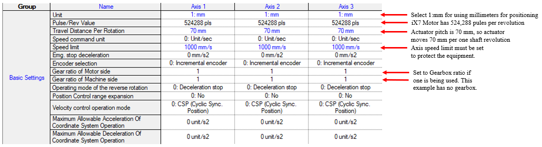
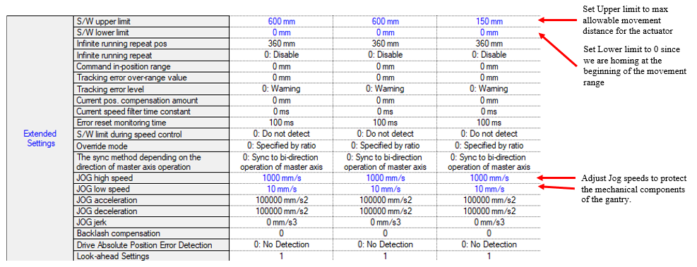
See Configuring Axis Parameters for configuring axis parameters. The basic axis parameter settings will define the interaction between the motion controller and servo drives. Units will be millimeters.
The gantry robot requires an axis group to be created. This axis group is used to configure which axes are part of the robot and the machine coordinate system. See Configuring Axis Groups in XG5000 for more information.
| Step | Action |
|---|---|
| 1 |
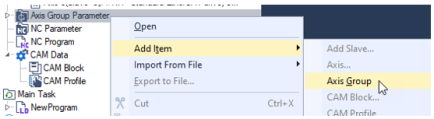
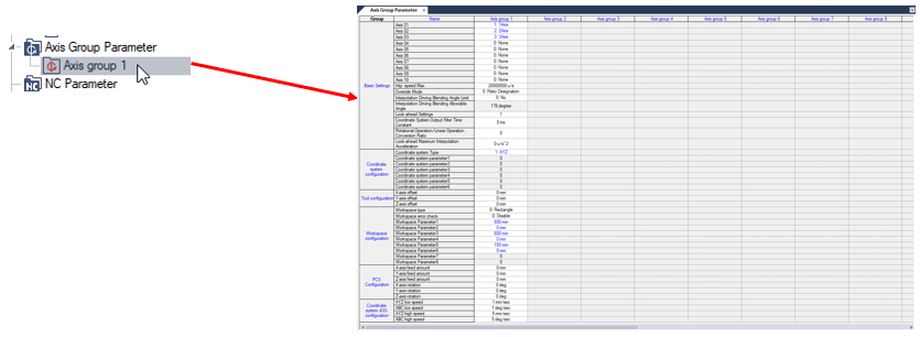
Right-click on Axis Group Parameter. Select Add Item è Axis Group.
|
| 2 |
Double-click on Axis group 1 to open up the Axis Group Parameters.
|
| 3 |
Add the axes to the group as shown below.
|
| 4 |
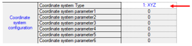
Set the Coordinate system Type to 1: XYZ for an XYZ gantry.
|
| 5 |
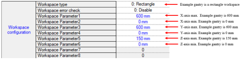
Configure the workspace for the gantry.
|
Sample program is XMC_XYZ_Gantry.zip
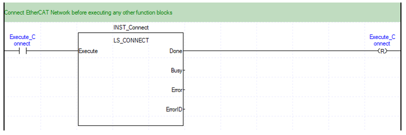
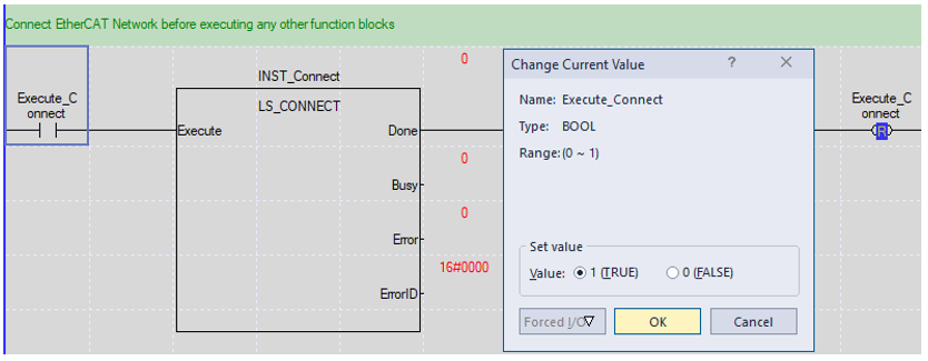
LS_Connect is used to connect the EtherCAT network and allow the XMC to control the servo drives.
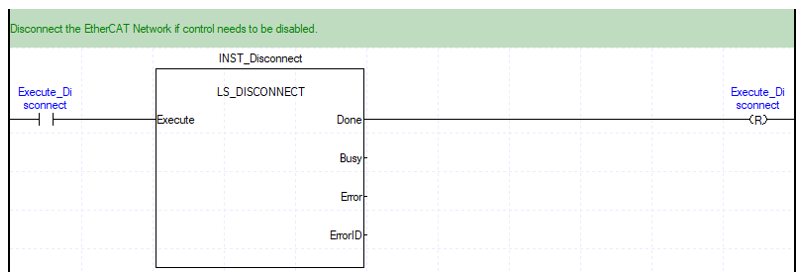
LS_Disconnect is used to disconnect the EtherCAT network and disable any control of the servo drives.
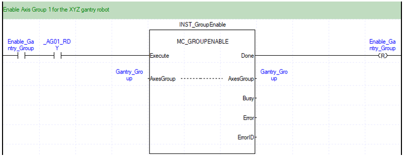
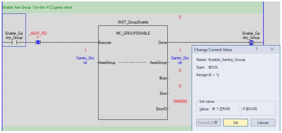
MC_GroupEnable is used to enable the group of axes assigned to the gantry.
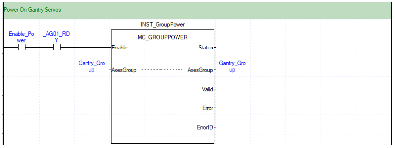
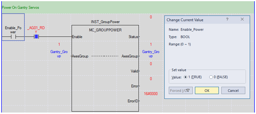
MC_GroupPower is used to turn on/off servos for axes in the group.
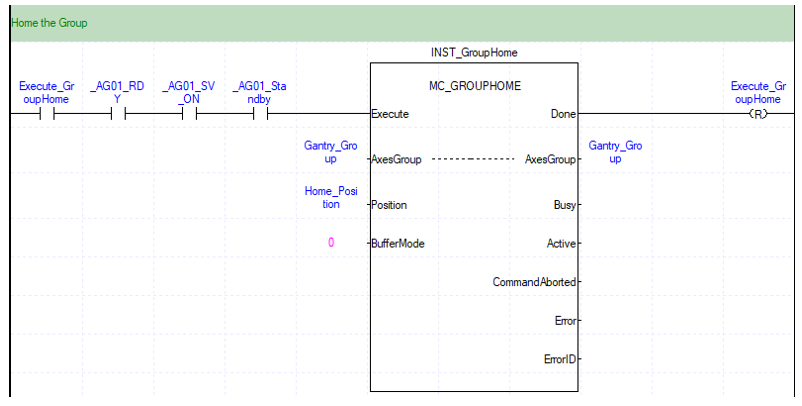
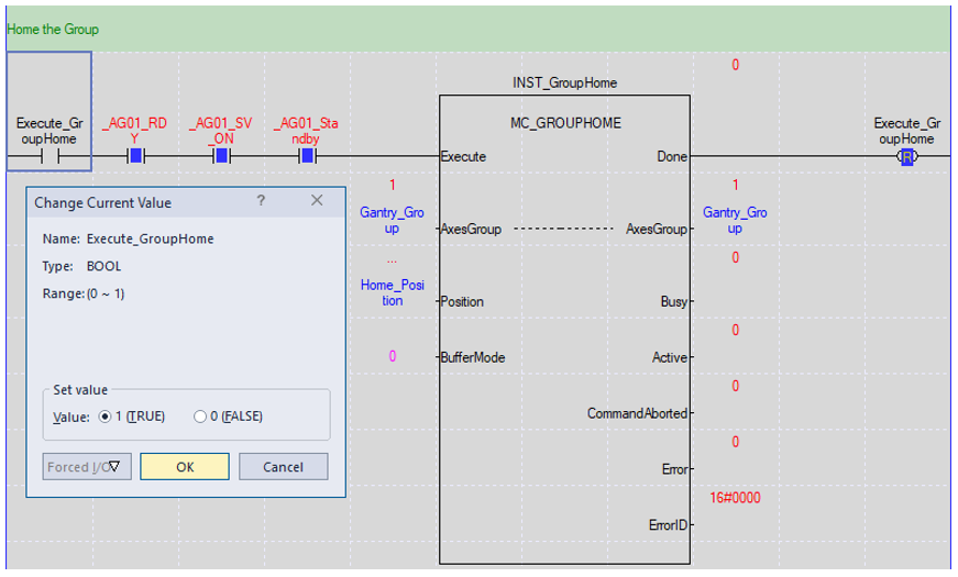
MC_GroupHome is used to home all the axes in the group.
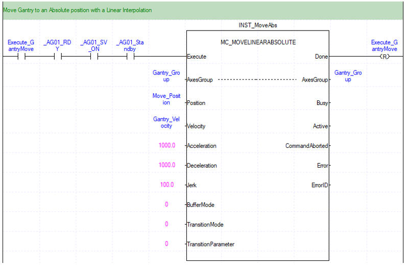
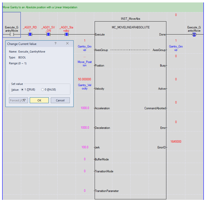
MC_MoveLinearAbsolute is used to execute an absolute interpolation movement of the gantry.
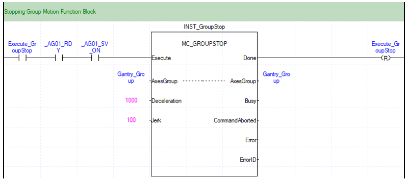
MC_GroupStop is used to stop any motion commands for the gantry group.
| Step | Action |
|---|---|
| 1 |
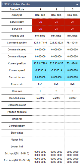
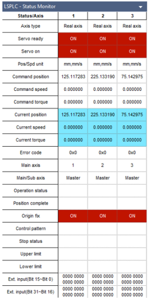
Set Execute_Connect to TRUE to execute LS_Connect Function block to connect the EtherCAT network. Note: Select the pull-down menu View è Status Monitor Window to open the Status Monitor window.
Status Monitor Screen will display axis information.
|
| 2 |
Set Enable_Gantry_Group to TRUE to execute MC_GroupEnable Function block to enable the group of axes for the gantry.
|
| 3 |
Set Enable_Power to TRUE to execute MC_GroupPower to turn on all servos in the gantry axis group.
Servo Status will change to ON.
|
| 4 |
Set Execute_GroupHome to TRUE to execute MC_GroupHome to home all axes in the group.
Origin Fix will change to ON.
|
| 5 |
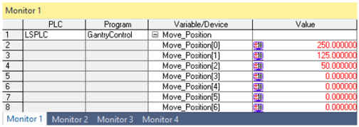
Add Move_Position to a monitor window. Enter a coordinate for the gantry to move to. Note: Move_Position[0] = X-Axis, Move_Position[1] = Y-Axis, Move_Position[2] = Z-Axis
|
| 6 |
Set Execute_GantryMove to TRUE to execute the group move.
|

LM1001