Configuring Axis Parameters
After adding motion based EtherCAT slaves, the axes associated with those slaves must be configured. These parameters should be configured for your specific application. XMC User Manual 5.1.3 contains more details about configuring axis parameters. Search for ‘(5) Axis parameter’ in the manual for quick access.
In the Project window, double-click on any axis in the Axis Parameter section. This will open the axis parameters for all assigned axes.
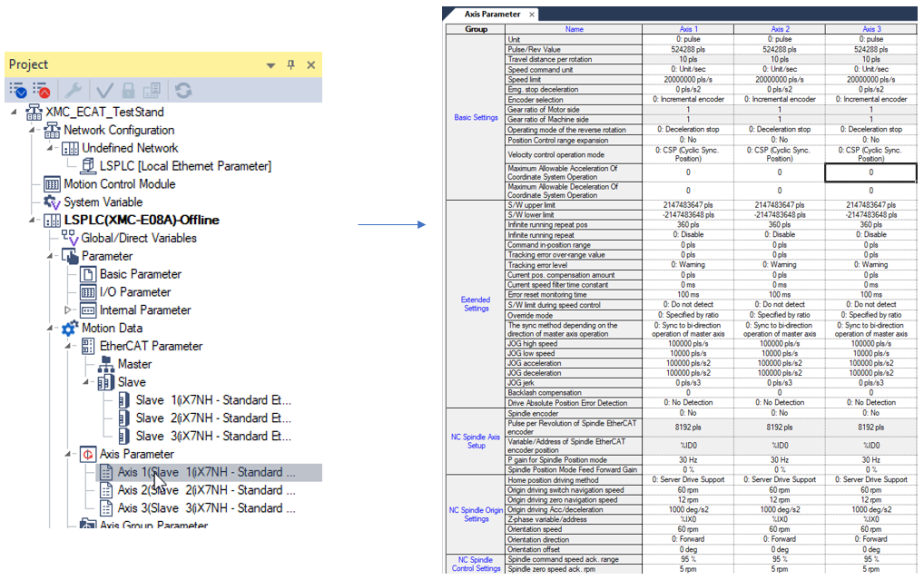
| Element | Name | Description |
|---|---|---|
| 1 | Axis | Axis Number for parameters in the column. |
| 2 | Unit | Unit can be set to pulse, mm, inch, or degree. |
| 3 | Pulse/Rev Value | Set the number of motor pulses for 1 revolution. |
| 4 | Travel distance per rotation | If unit is mm, inch or degree, set the amount of distance traveled per 1 revolution of the motor. |
| 5 | Speed command unit | Set speed command to unit/sec, unit/min, or rpm. |
| 6 | Speed limit | Set max speed of the Axis. |
| 7 | Emg. stop deceleration | Set to Emergency Stop deceleration rate. |
| 8 | Encoder selection | Choose if Encoder on the motor is incremental or absolute. |
| 9 | Gear ratio | Gear ratio values are available if using unit of mm, inch, or degree. |
| 10 | Operating mode of the reverse rotation | Choose the stopping method for a command that reverses the direction of motion. |
| 11 | Position Control range expansion |
|
| 12 | Velocity control operation mode |
|
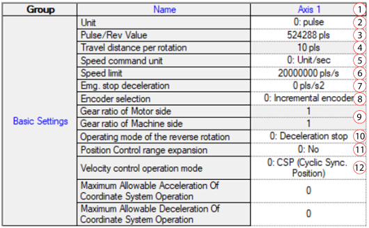
| Element | Name | Description |
|---|---|---|
| 1 | S/W upper limit | Set Software upper position limit. |
| 2 | S/W lower limit | Set Software lower position limit. |
| 3 | Infinite running repeat pos. | Ring mode position value. |
| 4 | Infinite running repeat | Enable ring mode position on the axis. |
| 5 | Command in-position range | Set the range for the in position signal to be on. See Command In-Position Range Setting for more information. |
| 6 | Tracking error over-range value | Set the range for tracking position deviation error |
| 7 | Tracking error level | Set the behavior for a position deviation error. Warning or Servo alarm are the options. |
| 8 | Current pos. compensation amount | Set the current position compensation amount. See Current Position Compensation Amount Setting for more information. |
| 9 | Current speed filter time constant | Set Speed filter time constant. See Current Speed Filter Time Constant Setting for more information. |
| 10 | S/W limit during speed control |
|
| 11 | JOG | Set Jogging Parameters. |
| 12 | Backlash compensation | Set Backlash compensation amount if applicable to your system. |
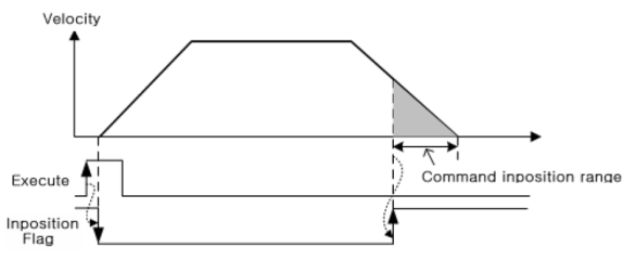
Command In-Position Range Setting
This setting will set the distance range from the commanded target position for the in-position flag (Axxx_INPOS) to turn on. The in-position flag will be off when motion control first starts. The in-position flag will turn on when the axis is at a position of Target Position + or – the Command inposition Range.
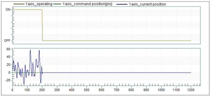
Current Position Compensation Amount Setting
Current position compensation can be used to remove jitter in current position when an axis is in standstill.
Current Position Compensation Amount = 0 pulses
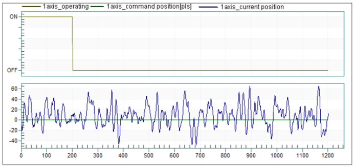
Current Position Compensation Amount = 100 pulses
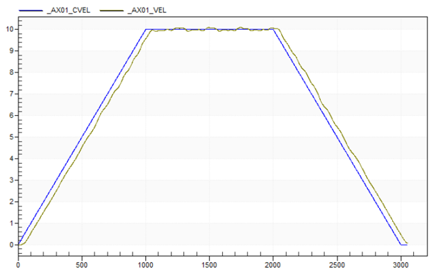
Current Speed Filter Time Constant Setting
This setting is used to add a filtering time to the current speed value. This can smooth out jitter in the current speed value.
Speed Filter Time = 0ms
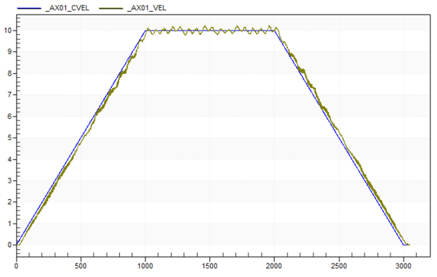
Speed Filter Time = 50ms
These settings are used for the NC system of the XMC motion controller. They can be left at default if not using the NC system.
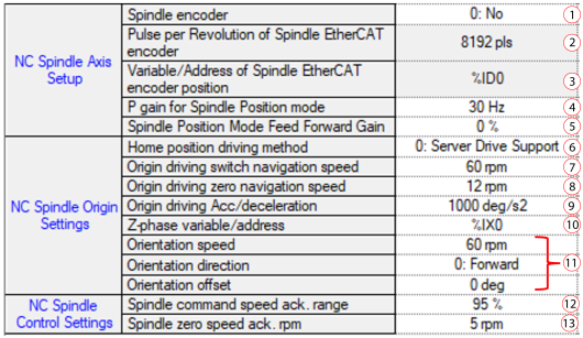
| Element | Name | Description |
|---|---|---|
| 1 | Spindle encoder | Select if the spindle motor has an encoder and how it is connected to the spindle axis. |
| 2 | Pulse per Revolution of Spindle EtherCAT encoder | Set Pulses/Rev if spindle encoder is setup as EtherCAT encoder. |
| 3 | Variable/Address of Spindle EtherCAT encoder position | Set the memory address of encoder position if spindle encoder is setup as EtherCAT encoder. |
| 4 | P gain for Spindle Position mode | Set the P gain of the spindle position mode. |
| 5 | Spindle Position MOde Feed Forward Gain | Set the feed forward gain value. |
| 6 | Home position driving method | Set the home search method for the spindle. |
| 7 | Origin driving switch navigation speed | Set the speed to search for the home switch. |
| 8 | Origin driving zero navigation speed | Set the speed to search for zero signal. |
| 9 | Origin driving Acc/deceleration | Set the acceleration/deceleration of the homing operation. |
| 10 | Z-phase variable/address | Set the device where Z phase signal is used as the zero signal. |
| 11 | Orientation | Orientation parameters when an M19 command is executed in the NC program. |
| 12 | Spindle command speed ack. range | Set the range where spindle is considered at rotation speed. |
| 13 | Spindle zero speed ack. rpm | Set the range where spindle is considered at zero speed. |
LM403