Topic: CL282

| Data Logging Setup |
Topic: CL282
|
CLICK PLCs with a microSD Card slot are capable of logging data from the PLC addresses. The Data Logging Setup provides the configuration tools for setting up the frequency of logging, data to be logged and file management.. The PLC can log data from any address except TXT data types. It can log up to 16 data points, at an interval set by the Trigger tag, to the inserted microSD Card.
There are also 14 System addresses listed in the dialog to aid in the control and monitoring of the data logging process.
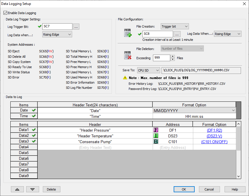
Enable Data Logging: Check the box to enable Data Logging for this project.
Log Trigger Bit : The Log Trigger Bit can be any Discrete Address in CLICK (X, Y, C, T, CT or SC). When this address transitions according to the "Log Data when..." setting, the PLC will write the values of the Data Log addresses to the SD Card. The fastest rate that data can be logged is 1 trigger/second.
Log Data when... : Select Rising Edge to log data when the Log Trigger Bit goes from low to high. Select Falling Edge to log data when the Log Trigger Bit changes from high to low.
System Address: The System Address shown in the dialog allow control and monitoring of the logging process.
Data Logging System Addresses Name Address Read Only /
Read/WriteDescription _SD_Eject SC65 Read/Write Set this bit ON to ask the system prepare to safely remove the SD card. The bit will turn OFF when the SD card is ready to be removed. _SD_Delete_All SC66 Read/Write Set this bit ON to ask the system to delete all log files on the SD card. The bit will turn OFF when the action is completed. _SD_Copy_System SC67 Read/Write Set this bit ONto ask the system to move the System Records from the PLC to the SD card. The bit will turnOFFwhen the action is completed. Error History, Failed Password Attempts Record, Email Log, Allow List Denied Record. _SD_Ready_To_Use SC68 Read Only ON when the SD card is "Ready to Use". _SD_Write_Status SC69 Read Only ON when writing data to the SD card. _SD_Error SC70 Read Only ON when there is a SD card error. SD69 will contain the error information. _SD_Total_Memory_L SD63 Read Only Stores the SD card Total Memory Available Low Word (megabyte) _SD_Total_Memory_H SD64 Read Only Stores the SD card Total Memory Available High Word (megabyte) _SD_Free_Memory_L SD65 Read Only Stores the SD card Free Memory Available Low Word (megabyte) _SD_Free_Memory_H SD66 Read Only Stores the SD card Free Memory Available High Word (megabyte) _SD_Used_Memory_L SD67 Read Only Stores the SD card Used Memory Available Low Word (megabyte) _SD_Used_Memory_H SD68 Read Only Stores the SD card Used Memory Available High Word (megabyte) _SD_Error_Information SD69 Read Only Stores the SD error number (see SD Card Error Codes) _SD_Log_File_Number SD70 Read Only Stores the current number of Log Files on the SD.
The File Configuration relates to file creation interval, file deletion Interval and the file location path.
File Creation:
Use One File: All logged data will be written to one file. Keep in mind, this file can become very large and difficult to retrieve.
Trigger Bit: The Trigger bit allows you to use logic with a discrete address or a System Bit to create a new log file. This allows management of files so they do not get too large and difficult to retrieve. The Trigger Bit can be any Discrete Address in CLICK (X, Y, C, T, CT or SC). When this address transitions according to the "Create File when..." setting the PLC will create a new data logging file on the SD Card. The fastest rate at which files can be created is 1 file/minute. The log file will be created even if the PLC is in Stop mode.
Create File when... : Select Rising Edge to create a new file when the Trigger Bit goes from low to high. Select Falling Edge to create a new file when the Trigger Bit changes from high to low.
File Deletion: Currently the only way log files are deleted is when the number of data logging files has exceeded the selected maximum number of files. The limit can be set at any quantity between 2 and 999 files. Once this limit is reached the oldest file will be deleted at the next File Creation trigger.
Save To: Currently the only selection is the SD Card slot in the CPU. The file will always be created in the \CLICK_PLUS\LOG\ folder on the SD Card. This folder will be created automatically if it does not exist. The Data will be saved to the file LOG_YYYYMMDD_HHMM_ddd.CSV, where YYYY, MM, DD, HH, MM and ddd are the Date and Time the file was created.
YYYY - Year
MM - Month
DD - Day
HH - Hour
MM - Minute
ddd- Day of the week (SUN, MON, TUE, WED, THU, FRI, SAT)
Data Logging Tips: These tips can prevent damage to the SD Card and lost data.
Monitor the _SD_Free_Memory addresses to make sure the SD Card does not fill up and cause data logging to stop.
Monitor the _SD_Log_File_Number address to make sure you know when it has reached 999 and old files are being deleted when each new file is created.
Always use the _SD_Eject to properly dismount the SD Card before physically ejecting it.
Make sure to monitor the _SD_Ready_To_Use and _SD_Write_Status and ensure they are off before physically ejecting the SD Card.
Always monitor the _SD_Error bit to make sure the SD Card and logging are working properly and to alert you of a problem.
microSD Card Selection
SD memory card selection is very important to preserve logged data with no errors.
It is recommended that an Industrial microSD Card is used that is rated for higher operating temperatures and heavier write loads.
microSD cards that utilize SLC technology are preferred. SLC Flash memory has the advantage of being the most accurate flash memory type when reading and writing data. SLC Flash has the longest lifespan of flash types and can operate in a broader temperature range than other types.
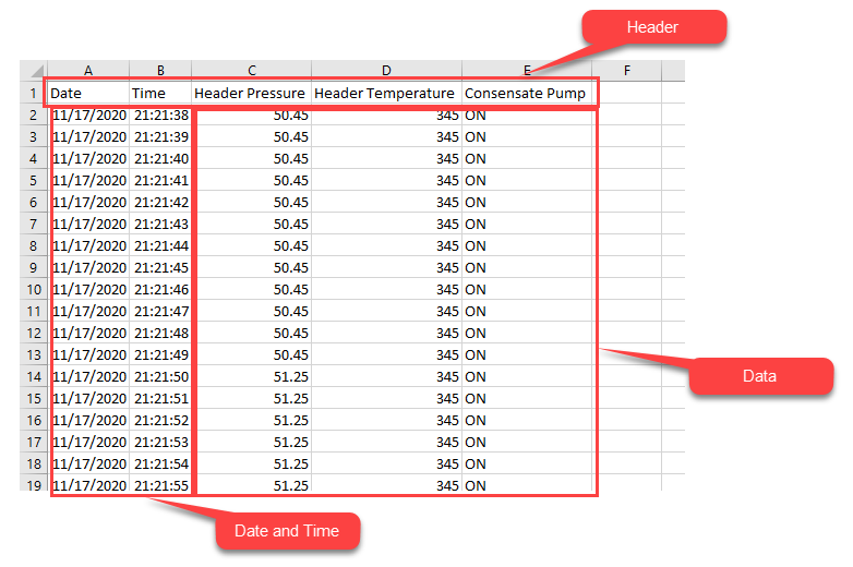
Items: The items that can be logged are the Date, Time and up to 16 Data Points.
Header Text: The purpose of the header text is to identify the data in each column. Each data point will have a column of data with the Header Text at the top. By default, the first two columns of data are the Date and the Time. These Data Points cannot be changed, but the header information can be changed.
Date: This text may be edited as desired. But this column will represent the Date the data point is logged. There are three different formats for the date that may be selected.
Time: Same as the Date header, this text can be edited, But this column represents the time the data point is logged. There is only one format : HH:MM:SS.

Note: Using DST (Daylight Saving Time) adjustments along with Data Logging may cause anomalies in the records. When the system time is adjusted backwards records may be lost or appended to existing files. When the system time is adjusted forward a time gap will appear in the records.
Header: This is where you enter the header text for each data point representing PLC data. It can be up to 24 characters long. If you do not enter a header, one will be automatically created as "Log Data #".
Address: This is the PLC address you wish to log. This can be any address in the PLC with the exception of TXT data types.
Format Options: Formatting is different for Discrete, Integer and Floating Point Data. See the Embed Discrete Address and Embed Memory Address topics for more information on formatting.
Data Log File Opened in Spreadsheet for Illustration