Topic: CL057

| System Configuration |
Topic: CL057
|
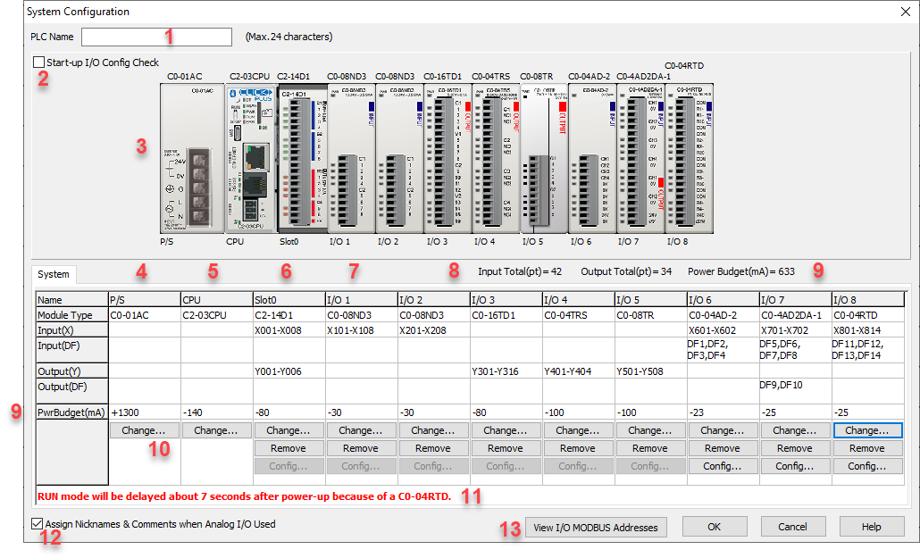
The System Configuration setup dialog displays the offline or online System Configuration and provides access to the setup dialogs for the PowerSupply, CPU, and I/O Modules.
When the PLC is Disconnected, the System Configuration setup dialog allows an offline manual setup.
![]()
1 PLC Name: Enter the Name of the CLICK PLC system. This field is not required.
2 Start-up I/O Config Check: Check this box to have the CPU Module check if the current System Configuration matches the Configuration registered in the project file. If there is a mismatch, the CLICK PLC won't turn on in the RUN mode.
3 Image of Configured System: Visual reference to confirm system configuration.
4 Power Supply Type: Current Power Supply selection is displayed. Click the Select/Change button to open the Select a Power Supply dialog to choose the power supply you are using. This selection is not required, but entering the power supply information allows the System Configuration tool to calculate the Power Budget for the entire system.
5 CPU Type: Current CPU selection is displayed. Click the Select/Change button to open the Select a CPU Module dialog.
6 Slot 0 I/O Type: For C2 Series CPUs, current Option Slot I/O Module selection is displayed. Click the Select/Change button to open the Select an I/O Module dialog.
7 I/O Type: Current I/O Module selection is displayed. Click the Select/Change button to open the Select an I/O Module dialog.
8 I/O Count: Total Inputs and Outputs of all modules combined.
9 Power Budget:The Power Budget for the existing configuration is displayed. If no power supply has been selected or the system's theoretical maximum current requirement exceeds the capacity of the power supply, the calculated current draw will be shown in red and the entire PwrBudget row will be red. If the systems theoretical maximum current does not exceed the capacity of the power supply, the value will be displayed in black.
10 Action Buttons: These buttons are enabled only when offline. When connected online with a PLC they are disabled and the configuration shows the configuration of the connected PLC.
11 System Information: If there is a C0-04RTD or C0-04THM in the CLICK PLC system, these modules need some time to complete the initialization process after power-up. The time period depends on the module type and the number of input channels used as shown in tables below..
C0-04RTD
| The Number of Channels Used | The same Input Type is selected for all channels | Mixed Input Types are Selected |
| 1 | 4 sec | N/A |
| 2 | 5 sec | May take up to 13 sec |
| 3 | 6 sec | May take up to 18 sec |
| 4 | 7 sec | May take up to 24 sec |
C0-04THM
| The Number of Channels Used | With any Configuration |
| 1 | 5 sec |
| 2 | 7 sec |
| 3 | 9 sec |
| 4 | 11 sec |
The CLICK Programming Software checks the module configuration and displays the info here.
|
|
Note: During the initiation process, the RUN LED on the CLICK CPU module keeps blinking. | |
12 Assign Nicknames and Comments when Analog I/O is Used: When this option is selected, the CLICK Programming Software automatically assigns the predefined nicknames and address comments to the allocated X-memory addresses of the analog I/O modules as status indicators.
Example 1: A C0-04AD-1 is installed in the I/O5 position. (Other analog I/O modules, except the C0-04RTD and C0-04THM, are the same.)
| X Memory Address | Nickname | Address Comment |
| X501 | _IO5_Module_Error | On when module is not functioning |
| X502 | _IO5_Missing_24V | On when missing external 24V input |
Example 2: A C0-04RTD is installed in the I/O7 position. (The C0-04THM is the same.)
| X Memory Addres | Nickname | Address Comment |
| X701 | _IO7_Module_Error | On when module is not functioning |
| X702 | _IO7_Module_Config | On when module is initializing |
| X703 | _IO7_CH1_Burnout | On when CH1 senses burnout or open circuit |
| X704 | _IO7_CH1_Lower_Range | On when CH1 receives under range input |
| X705 | _IO7_CH1_Upper_Range | On when CH1 receives over range input |
| X706 | _IO7_CH2_Burnout | On when CH2 senses burnout or open circuit |
| X707 | _IO7_CH2_Lower_Range | On when CH2 receives under range input |
| X708 | _IO7_CH2_Upper_Range | On when CH2 receives over range input |
| X709 | _IO7_CH3_Burnout | On when CH3 senses burnout or open circuit |
| X710 | _IO7_CH3_Lower_Range | On when CH3 receives under range input |
| X711 | _IO7_CH3_Upper_Range | On when CH3 receives over range input |
| X712 | _IO7_CH4_Burnout | On when CH4 senses burnout or open circuit |
| X713 | _IO7_CH4_Lower_Range | On when CH4 receives under range input |
| X714 | _IO7_CH4_Upper_Range | On when CH4 receives over range input |
13 View I/O MODBUS Addresses: Select this button to open the I/O Modbus Addresses window. This dialog box is a table of all the Modbus addresses assigned to each Input and Output. The addresses can be viewed in Modbus 984 or HEX formats. Also from this dialog the address list can be exported to a CSV file.
