AutomationDirect SOLO Modular Temp Controller Setup |
Topic: CM161 |
This SOLO Modular temperature controller driver allows C-more to easily and directly access the SOLO Modular parameters for viewing and/or adjustment over a serial connection.
Check SOLO Communications Parameters
The serial communication settings are shown below and should be set to match the settings in the C-more Programming Software Protocol Manager window.
To check or change the serial communication parameters in SOLO, use the Solo Configuration software to set Parameters (P3-xx).
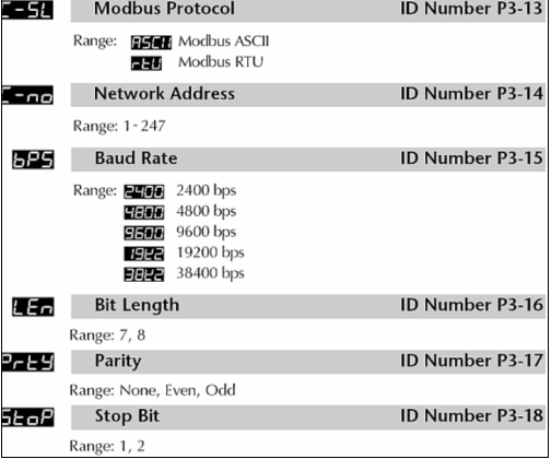
- Parameter P3-13 must be set to RTU in order for C-more to be able to communicate to the controller.
- Parameters P3-P14, P3-15, P3-17,and P3-18 need only match the Protocol Manager settings.
- Parameter P3-16 must be set to 8.
C-more Protocol Manager Settings
- Do one of the following:
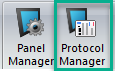
- Click the Protocol Manager button on the Home tab
— or — - Click the Protocol Manager button on the Setup tab
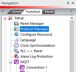
— or — - from the Navigation window, click the Function tab, click Setup and then select Protocol Manager.
- From the Protocol Manager window, click the Device name on the tree to the left.
- The Device Setup window opens.
- In the PLC Protocol field, click on the down arrow
 and select AutomationDirect SOLO Modular Temp Controller.
When you select a different PLC Protocol than the one currently in use, the warning Message shown below appears.
- Click Yes to accept.
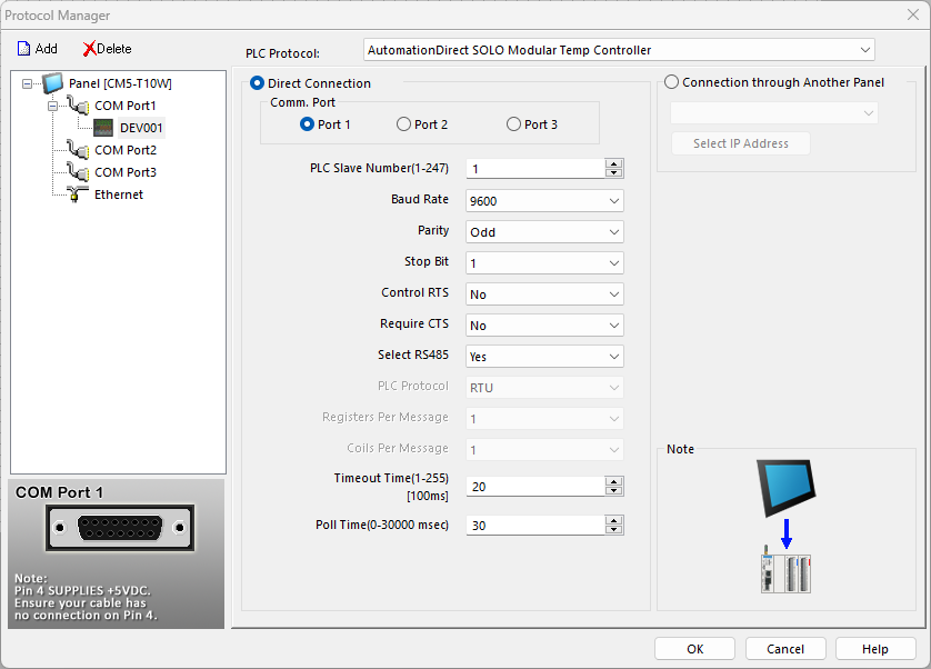
The AutomationDirect SOLO ModularTemp Controller Protocol Manager window provides the Data described below.
PLC Protocol Settings
PLC Slave Number (0-255)
The Slave Address of the SOLO Modular controller. Match the value set in parameter P3-14 of the SOLO Modular controller that is connected to C-more.
Baud Rate
Match the Baud Rate set in parameter P3-15 of the SOLO Modular controller.
Parity
Match the parity settings in parameter P3-17 of the SOLO Modular controller.
Stop Bit
Match the Stop bit setting configured in parameter P3-18 of the SOLO Modular controller.
Control RTS
Select Yes in this drop-down to assert the C-More panel RTS signal before every serial transmission for the purpose of using a RS-232 to RS-485 converter or modem.
Also, select Yes if the RS-422 driver signal needs to be turned OFF at the end of transmission.
The default is No, based on connecting to a port with the RTS and CTS signals jumpered together.
Require CTS
Select Yes in this drop-down If using a modem on the C-more serial port for flow control. Otherwise, leave this setting at No.
Select RS 485
Select Yes for this field. The SD+ and RD+ must be jumpered and the SD- and RD- pins must be jumpered. This setting is on by default since the SOLO Modular controllers use 2 wire RS-485 as their method of serial communication.
PLC Protocol, Registers Per Message, and Coils Per Message
These fields are read only.
Timeout time (1-255) [100msec]
The time (in 100 millisecond increments) the C-more Panel waits for communications with the PLC before it displays an error. 30 tenths of a second (3 seconds) is the default and should not require adjustment.
Poll Time (0-30000 msec)
The amount of time (in milliseconds) that the panel waits in between each request.
Connection Through Another Panel
You can configure this protocol for any PLC supported by C-more panels.
You can connect a C-more panel to other C-more panels on your network via an ethernet connection. This type of connection is also known as a Pass Through Connection.
Go to Connection Through Another Panel (Pass-Through) to learn more about Pass Through and using Connection Through Another Panel.
