|
|
Topic: P314 |
Rotary Table Application (RTA) |
|
|
|
Topic: P314 |
Rotary Table Application (RTA) |
|
Icon / Button =
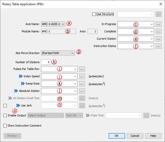
The Rotary Table Application (RTA) instruction is used to control a station-based rotary application. Many of these applications exist in the automation control industry and the goal here is to make it easy for a user to setup and use. The user is required to enter the number of stations, the raw number of pulses per revolution of the table, and the speed and ramp of the indexing moves.
|
Parameter |
Parameter Type |
Requirements |
Description |
|
Enable |
Ladder Input |
Must Have |
Level-driven. When Enable is ON, the instruction will operate every scan. When Enable is OFF, the instruction is not solved and its Outputs are not updated. |
|
Axis Name |
Selectable Dropdown |
Must Have |
The selected axis this instruction will control. Each AMC module will have from 1 up to 4 depending on the model number. |
|
Abs Move Direction |
Selectable Dropdown |
Must Have |
Select Shortest Path, Always Move Forward or Always MoveReverse. By default, the shortest path will be used to determine the move direction. The other selections will always go their respective directions regardless of distance. |
|
Number of Stations |
Constant |
Must Have |
Set to the number of evenly spaced stations in each revolution.(minimum of 2 stations required) |
|
Pulses per table revolution |
Numerical Tag |
Must Have |
Set to the raw number of pulses per table revolution. This value is NOT scaled. |
|
Index Speed |
Numerical Tag |
Must Have |
Sets the speed of the trapezoidal index moves. This value can be changed while the instruction active. If changed, the new will be used on the next index move after the change is received. |
|
Ramp Rate |
Numerical Tag |
Must Have |
Sets the symmetrical accel and decel of the trapezoidal index move. This value can be changed while the instruction is active. If changed, the new dwell time will be used on the next index move after the change is received. |
|
Absolute Station |
Numerical Tag |
Optional |
Enter the value of the Target Station ID when the Abs Input is triggered |
|
At Station Dwell Time |
Numerical Tag |
Optional |
(Option Enabled if Output Pulse Time selected) When the move is completed the specified dwell time will begin. Once complete the assigned Output will enable. If changed, the new value will be used on the next index move after the change is received. |
|
Use Jerk |
Numerical Tag |
Optional |
When selected, a Jerk value is required. The indexing move will now have s-curve ramps. If used, this value can be changedwhile the instruction is active. If changed, the new value will be used on the next index move after the change is received. |
|
Enable Output |
Checkbox |
Optional |
Enables the Output Control feature. |
|
Output Pulse Time |
Numerical Tag |
Optional |
Select either Turn On, Turn Off, Pulse On, or Pulse Off. If either pulse option is selected, the pulse time parameter must be defined. When selected, the user will have to choose one. When selected, the pulse width, in msecs, will be required and can be changed when the instruction is active. Also, Delay Time is optional and is used to delay the GP output signal from the end of the index move. The signal of the output can be changed while the instruction is active. When left blank, the signal is triggered at the end of the index move. Both the Delay time and the pulse width time can be updated every scan and will be used on the move that starts immediately after the new value is received. |
|
In Progress |
Boolean |
Optional |
A Status tag that indicates whether or not the instruction is active. The AMC module runs asynchronously with respect to the ladder scan so this status should be used for interlocking logic if necessary. This tag is immediately set to 1 when this instruction is enabled unless the axis is currently executing another instruction. When the instruction is complete , this tag is set to 0. |
|
Complete |
Boolean |
Optional |
A Status tag that indicates the execution of this instruction was completed successfully. The AMC module runs asynchronously with respect to the ladder scan so this status should be used for interlocking logic if necessary. This tag is immediately set to 1 when this instruction is complete. When this instruction is enabled successfully, this tag is set to 0. |
|
Current Station |
Numerical Tag |
Optional |
Holds the value of the current/last station where motion stopped. |
|
Instruction Status |
Numerical Tag |
Optional |
A Status tag that contains the Feedback of the Action being performed by this instruction. The high-speed modules run asynchronously with respect to the ladder scan so this status should be used for interlocking logic if necessary. See the Instruction Status Table for bit definitions. |
Note : This instruction assumes that all the stations are equally spaced.
Note: Before using this instruction, the axis should be successfully homed and moved into the location of station one. Every subsequent move will be based off that location until the instruction is disabled.
Note: The instruction may not function correctly if the axis is being used in another instruction in ladder. If two separate instructions in ladder use the same axis, the latest one [in the scan cycle(s)] controls the axis.
Note : The
"On-the-fly" symbol
 indicates that this value can be changed while the instruction is
running.
indicates that this value can be changed while the instruction is
running.
|
Instruction/ Feature Abbreviation |
Instruction/ Feature Name |
Structure Element |
||
|
|
Field |
Name |
Default Type |
|
|
RTA |
Rotary Table |
In Progress |
In Progress |
Boolean |
|
Complete |
Complete |
Boolean |
||
|
Status |
Instruction Status |
Integer, 32-bit |
||
|
PulsesPerRev |
Pulses Per Revolution |
Float, 32-bit |
||
|
IndexSpeed |
Index Speed |
Integer, 32-bit |
||
|
RampRate |
Ramp Rate |
Integer, 32-bit |
||
|
JerkRate |
Jerk Rate |
Integer, 32-bit |
||
|
AbsStation |
Absolute Station |
Integer, 32-bit |
||
|
OutputPulseTime |
Output Pulse Time |
Integer, 32-bit |
||
|
StationDwellTime |
Station Dwell Time |
Integer, 32-bit |
||
|
CurrentStation |
Current Station |
Integer, 32-bit |
||
This instruction (shown below) has four sub rungs for control:
|
Status |
Description |
|
| 1 |
Px-HSO: Accelerating |
This bit shows the current state of the channel while movement is accelerating (when In Progress Bit = ON). After the instruction is Complete, this bit will be OFF. |
|
PS-AMCx: General Use Status 1 |
AREG: Waiting For Master Event |
|
|
FCO: Waiting for Event Start |
||
|
GEAR: Primary Drivetrain Slave is Enabled |
||
|
MREG: Correction Move In Progress |
||
|
MSEQ: Dwell Period of Timeout is Active |
||
|
RTA: Table stopped at station |
||
| 2 |
Steady Velocity |
This bit shows the current state of the channel or axis while movement is running in steady state (when In Progress Bit = ON). After the instruction is Complete, this bit will be OFF. |
| 3 |
Px-HSO: Decelerating |
This bit shows the current state of the channel while movement is decelerating (when In Progress Bit = ON). After the instruction is Complete, this bit will be OFF. |
|
PS-AMCx: General Use Status 2 |
AREG: Waiting For Product Event |
|
|
FCO: Tool Slewing to Synchronization |
||
|
GEAR: Secondary Drivetrain Slave is Enabled |
||
|
RTA: Alert: Invalid Absolute Station Id |
||
| 4 |
Px-HSO: Future |
Future |
|
PS-AMCx: General Use Status 3 |
AREG: Correction Applied |
|
|
FCO: Tool is in Synchronization with the Master |
||
|
GEAR: Third Drivetrain Slave is Enabled |
||
|
MREG, SMOV, VMOV: Position Capture Occurred (1 or 2 scan pulse) |
||
| 5 |
Px-HSO: Future |
Future |
|
PS-AMCx: General Use Status 4 |
GEAR: Fourth Drivetrain Slave is Enabled |
|
| 6 |
Px-HSO: Future |
Future |
|
PS-AMCx: Application Move |
Info – Application Move is in Progress (Movement or active slave ) |
|
| 7 |
Stopped at Move Target |
This bit is ON when the instruction completes and the Target position was achieved without any Errors or Aborts. |
| 8 |
Stopped at Registration Target |
This bit is ON when the instruction completes a Registration function using the Decel to a Stop option without any Errors or Aborts. |
| 9 |
Aborted - Instruction Disabled |
This bit indicates that the instruction was disabled in the ladder by the user |
| 10 |
Aborted - Hit Limit (See Channel or Axis Status Register) |
This bit indicates that either a Limit Switch or Position Limit has been tripped. The Channel or Axis Status will indicate which of the 4 possible conditions has occurred. |
| 11 |
Aborted - Communications Failure During Move |
This bit indicates that communication to the module failed previously. The module may now be ready but the current instruction must be restarted. This condition may occur due to a hot-swap or a loss of communication to a Remote Slave Base. |
| 12 |
Aborted - IO Fault (See Module Error Register) |
If the ESCP (Electronic Short Circuit Protection) becomes active for the Output Channels associated with the current instruction, the instruction will abort since the intended operation will fail. This bit will turn ON and the specific Channel error can be found in the Module Error Code, Bits 2 & 3. Note: Faults on Channels 3-6 will not cause this abort and must be detected using the Channel Status and Module Error Code. |
| 13 |
Aborted - Over User's Max Accel |
In the HSO H/W Configuration Channel setup or the PS-AMC Axis Configuration, the user has the option to either Limit a move to a maximum value or Stop the move once that maximum value is exceeded. If the Channel or Axis is configured to Stop the Move and the instruction exceeds the Maximum value, the instruction will Abort and one of these related bits will turn ON. |
| 14 |
Aborted - Over User's Max Decel |
|
| 15 |
Aborted - Over User's Max Velocity |
|
| 16 |
Px-HSO: Aborted - Position Limit out of range |
If the tag values assigned to the Position Limits are out of range, the instruction will Abort and this bit will be ON. Note: Affected by Channel Scaling. |
|
PS-AMCx: Future |
Future |
|
| 17 |
Px-HSO: Aborted - Target out of range |
When Position Limits are configured and the Instruction Target position is known to be beyond the Position Limits, the Instruction will Abort before any motion starts and this bit will be set ON. Note: Affected by Channel Scaling. |
|
PS-AMCx: Abort Invalid Input/Edge Combination |
This will occur when an axis is configured for RPI ( Reset Position by Input ) and that axis is running an instruction ( or it’s slave ) and tries to use the same input as RPI with a different edge. |
|
| 18 |
Aborted - Velocity out of range |
The HSO outputs can be run at a maximum of 1MHz. If the instruction commands a velocity greater than 1MHz, the instruction will Abort with this bit ON. Note: Affected by Channel Scaling. |
| 19 |
Aborted - Accel/Decel/Ramp out of range |
If the value assigned to the Acceleration or Deceleration Ramp is outside the valid range (1 to 100e6), the instruction will Abort and this bit will be ON. >Note: Affected by Channel Scaling. |
| 20 |
Aborted - Jerk/S-Curve out of range |
If the Jerk value is outside the valid range of 1 to 100e9or the S-Curve value is outside the range of 1 to 100e6, the instruction will Abort and this bit will be ON. Note: Affected by Channel Scaling. |
| 21 |
Px-HSO: Future |
Future |
|
PS-AMCx: Axis Status |
Additional information will be stored in the Axis Status register tag |
|
| 22 |
Px-HSO: Future |
Future |
|
PS-AMCx: Aborted - General Parameter |
There is a general parameter out of range ( does not include velocity, ramps, jerk, registration, or presets ) |
|
| 23 |
Px-HSO: Future |
Future |
|
PS-AMCx: Aborted – Preset Parameter |
There is a preset parameter out of range |
|
| 24 |
Aborted - Registration parameter out of range |
At least one of the Registration input parameters is out of range. Parameters such as: Delay Registration Action by, Decel to a Stop or Output Pulse Time. |
| 25 |
Alert - Target reached during Accel/Decel |
If a home switch is reached while accelerating or decelerating, this bit will be set. To ensure repeatable accuracy, you must adjust your parameters or move further away from home and re-home so that the switch is reached at a steady speed. |
| 26 |
Alert - Parameter Adjusted: Over User's Max Accel |
In the HSO H/W Configuration Channel setup, the user has the option to either Limit a move to a maximum value or Stop the move once that maximum value is exceeded. If the Channel is set to Use the Maximum Value and the instruction exceeds this value, the instruction will not Abort and the output will be limited to the Maximum Value with the related Alert bit set to ON. |
| 27 |
Alert - Parameter Adjusted: Over User's Max Decel |
|
| 28 |
Alert - Parameter Adjusted: Over User's Max Velocity |
|
| 29 |
Px-HSO: Alert - Position Rolled Over |
These bits are set to report the occurrence of a Roll Over and/or Roll Under. They will remain set for 3 scans and then clear. This makes it possible to detect multiple roll over and/or roll under events using ladder code. The default rollover positions are +/- 2,147,483,647 but Channel Scaling affects this range and if Rotary Mode is enabled, the range will always roll under at zero, and roll over to zero. |
| 30 |
Px-HSO: Alert - Position Rolled Under |
|
| 31 |
Future |
Future |
| 32 |
Future |
Future |


 changed while the instruction is active.but will not be used
until the next index move after the change is received.
changed while the instruction is active.but will not be used
until the next index move after the change is received.