|
|
Topic: P305 |
User Defined Structures |
|
|
|
Topic: P305 |
User Defined Structures |
|
User Defined Structures are an extremely powerful feature of the Productivity Suite software that improves the maintainability, uniformity, and readability of your routines. Simply put, a User Defined Structure is a collection of Data Types defined by the user.
User Defined Data Types allow you to create a data structure for a particular part of your system. You can then use that data structure throughout your project. Examples of where you might use a UDS would be when you have multiple motors, pumps, or valves in a project.
Data Types are just “Menu Items”. When you walk into a restaurant, and order a #1 Value meal, the cashier knows exactly what you want. You don’t have to specify each item individually. It’s the same with Data Types. When you create a tag, and give the tag a Data Type, Productivity Suite knows exactly how to structure that tag.
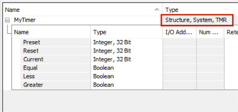
Before we get into UDSs, let’s take a look at a pre-defined Data Type that you already understand. The timer Data Type is already defined by default in a project. The timer is PREDEFINED. When you create a tag, and give it a TMR Data Type, its data structure includes the Preset, Reset, Current, Equal, Less and Greater values.
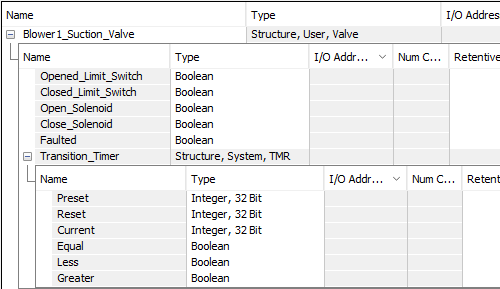
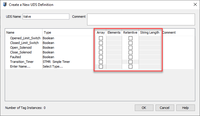
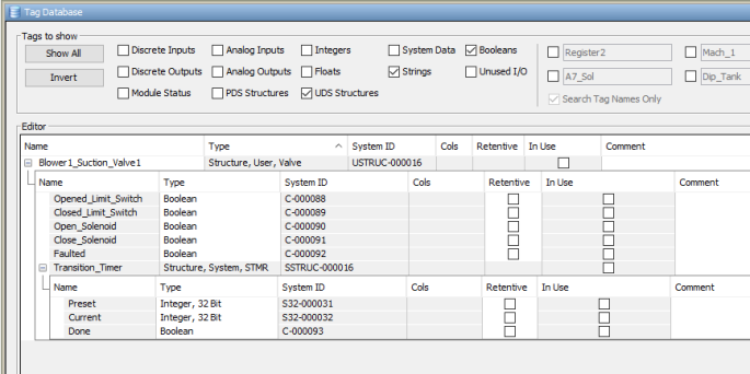
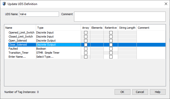
An example of a USER DEFINED data structure is a valve. You might have ten valves in your system, and each valve would have the same data structure. Each valve would have an Opened and Closed Limit Switch, Open and Close Solenoid, fault bit, fault timer, etc. Instead of creating each individual tag for every valve, you can create a valve Data Type. Then any time you need to use a valve, you can name the valve, and give it the valve Data Type. The tag would then inherit everything we need for a valve.
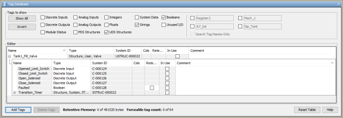
Here is what you might end up with for a tag with a valve Data Type after it’s been created: (We’ll create this type in the steps below).
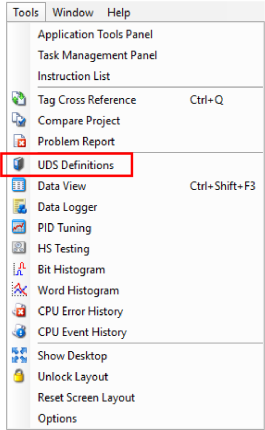
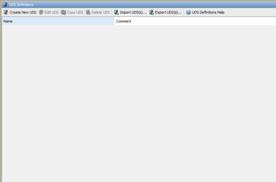
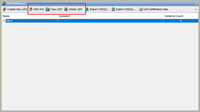
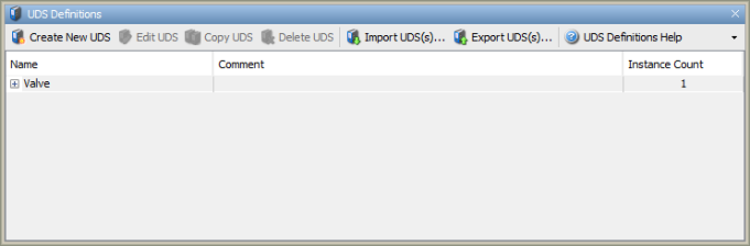
The UDS Definition window is accessed by selecting Import UDS(s) from the Tools Menu or by selecting UDS Definitions from the Write Program folder of the Application Tools panel.
Once selected, a UDS Definitions window will open as shown below:
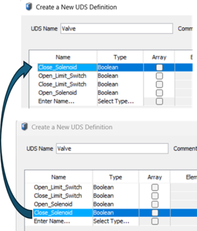
To create a new User Defined Structure definition, follow these steps:

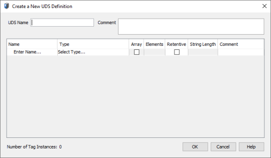
- Array
- Number of Array Elements
- Retentive
- String Length (for elements of String data type)
Note:Nesting of up to 4 UDS definitions is supported.
Note:Predefined Data Types supported.
.
To Edit, Copy, or Delete, select a UDS Definition and click the appropriate icon.
A UDS Definition, by itself, has no function in program logic. It's simply a definition that "defines" the data type of the individual elements. Then, you create a tagname that references the UDS Definition. The next few topics show you how to create a "UDS tag" that can be used in your program logic.
To create a tag using a User Defined Structure Definition , follow these steps:
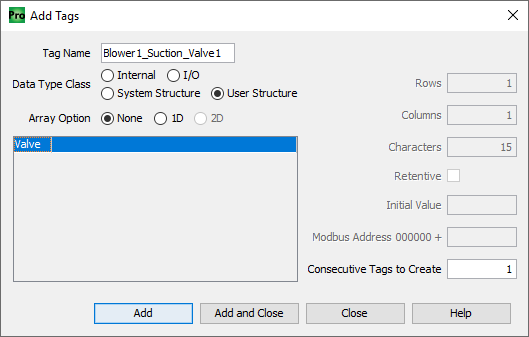
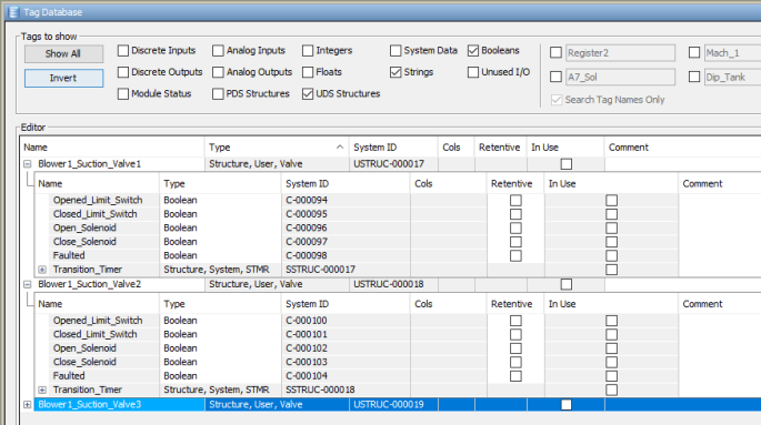
The Tag Blower1_Suction_Valve1 is created and has all of the elements of the UDS Valve.
Reordering of UDS elements can be accomplished by dragging and dropping a tag to a new location in a UDS definition.
Note:The maximum size of each element of a tag using a UDS is 32 characters.
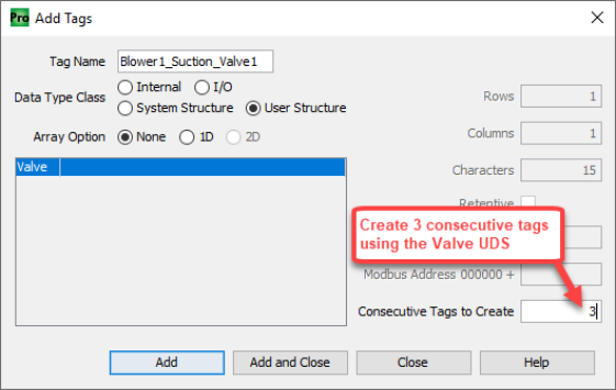
The "Consecutive Tags to Create" option can be beneficial when creating Tags with User Defined Structures. In the example below Blower #2 has three Suction Valves. By naming the Tag Blower1_Suction_Valve1 and selecting 3 for Consecutive Tags to Create, Tags for all three valves are created.
Productivity Suite version 3.7 introduced the Array data type as part of a UDS Definition. You can now create a UDS Definition Element designated as a one-dimensional array as well as create an Array of Tags with a UDS data type containing arrays.
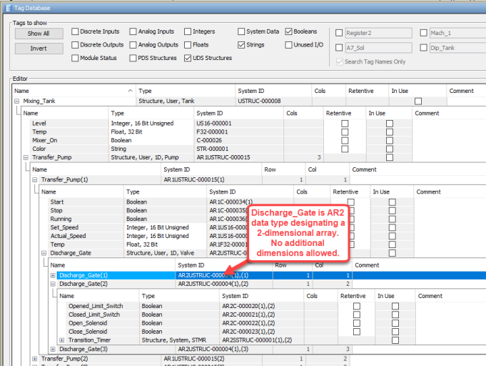
The four level nesting limit for User Defined Structures still applies for a UDS containing array data types, BUT with the additional requirement that an array cannot exceed two dimensions. The array can belong to any Level of the Nested UDS (see examples: L1-L4=nest level, (x)= element of array).
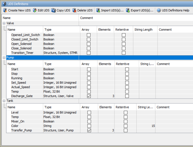
Now suppose we have a Mixing Tank with 3 Transfer Pumps. Each Transfer Pump has 3 possible Discharge Gates. We can create UDS Definitions containing arrays to make short work of configuring all the tags needed for the Mixing Tank.
First, create the UDS Definitions:
Second, in the Tag Database create a Tag for a Mixing Tank.
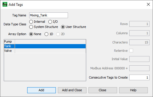
Result:
Tags created from UDS Definition Tank, i.e.
Mixing_Tank.Transfer_Pump(1).Discharge_Gate(2).Closed_Limit_Switch
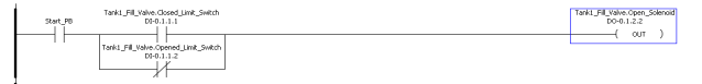
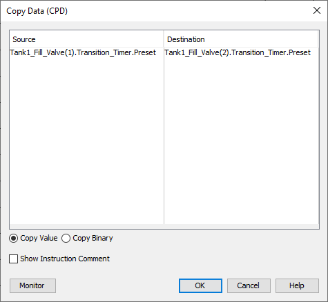
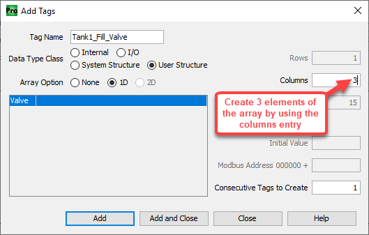
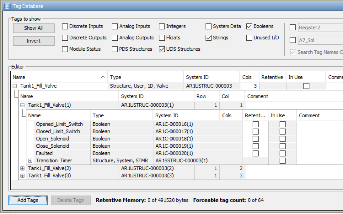
The advantage of creating an Array of UDS Tags is to provide a way to Index the Tags. In the example below, Tank1 has three Fill Valves. We enter the Tagname Tank1Fill_Valve, select UDS definition Valve, select 1D Array Option and 3 Columns.
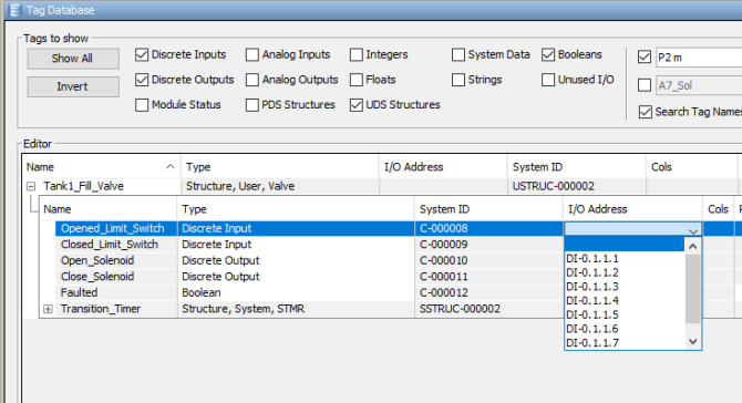
In previous examples for ease of explanation we used Boolean Data Types for some UDS elements that would normally be used as Hardware I/O Data Types. In this example we will edit the UDS definition to change the Boolean elements to Discrete Inputs and Outputs.
Note: This is a UDS definition - we don't assign the actual I/O point here.
Note: When creating an array of user-defined structures (UDS), the System and Module data types cannot be defined.
Elements of existing or new UDS Tags that are configured for UDS Valve Type are now assigned Discrete Input/Discrete Output as Datatype (note that system ID is still assigned a C - internal Boolean).
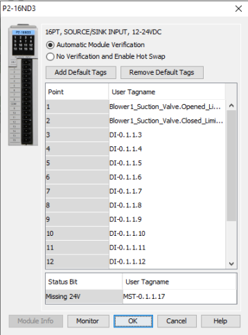
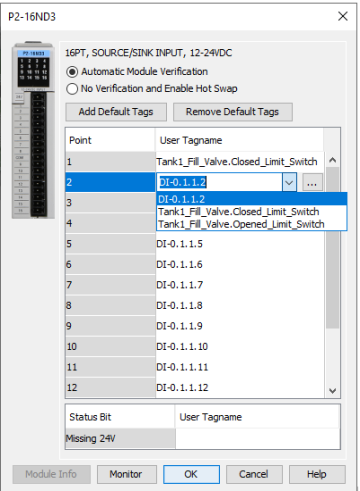
The next few steps will show how to assign the elements of the UDS to I/O points in the Tag Database or the Hardware Configuration.
Note: Only I/O addresses that have no assignment in the Hardware Configuration will appear as selections in the I/O address field in the Tag Database.
OR