|
|
Topic: P283 |
EtherNet/IP EDS file import |
|
|
|
Topic: P283 |
EtherNet/IP EDS file import |
|
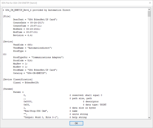
An
Electronic Data Sheet (EDS)
is an ASCII text file that describes the features of an
An EtherNet/IP Client device is created and configured to communicate with a specific EtherNet/IP Adapter device. You can create an EtherNet/IP device by three possible methods:
Note: The following Class 1
connection types (application types) are supported:
* Exclusive Owner
* Input Only
* Listen Only
* The following transport trigger is supported
* Cyclic Trigger
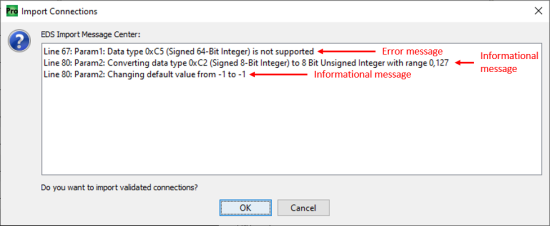
Note: Common import errors are due to unsupported data types, server connections, etc. Not all messages are errors, but may offer useful information regarding any required modifications that are being done during import.
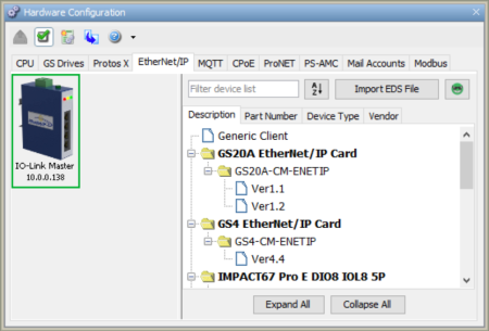
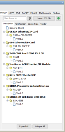
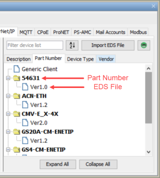
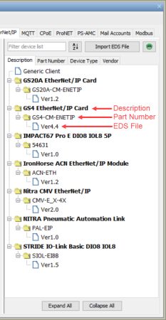
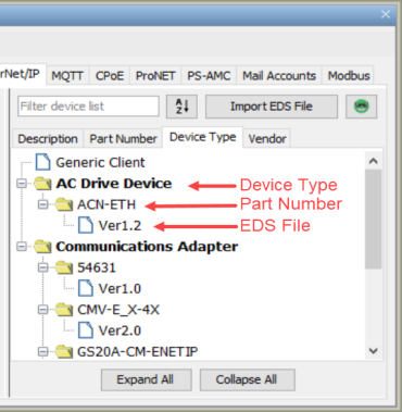
Note: The EDS library is
organized into 4 tabs - Vendor, Part Number, Description, and Device
Type:
* Vendor is listed under [Device] VendName in .EDS file
* Part Number is listed under [Device] Catalog in .EDS file
* Description is listed under [File] DescText in .EDS file
* Device Type is listed under [Device] ProdTypeStr in .EDS file
Once Imported the device will now be listed and searchable in the EDS library.
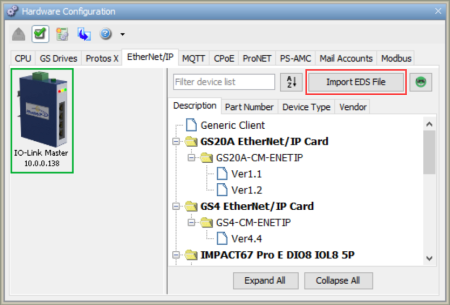
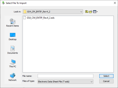
After selecting Import EDS file, browse for an EDS file:
If no errors were found during import, the EDS file is placed in the library.
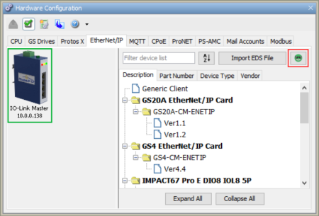
Note: Productivity Software comes with EDS Files preloaded in the EDS Library. These files can be deleted by the user and may also be re-imported by clicking on the "Smiley Guy" icon.
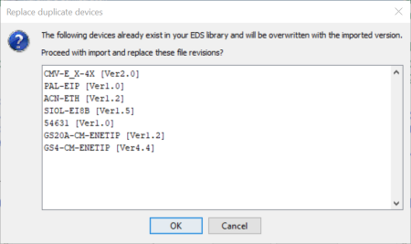
A dialog window will open asking if the user wants to proceed with importing and replacing the listed EDS file revisions.
Note: Imported EDS files are
stored globally across software versions.
1. Devices added via EDS file import prior to Productivity Software,
Version 3.11:
* Will be available to new and old versions of the software
* Will appear in the “Uncategorized” folder in all tab views for
versions 3.11 and later
* Will NOT have the “View EDS file” feature available in versions
3.11 and later
* Will NOT be included when performing an “Export EDS file library”
in versions 3.11 and later
2. Devices added via EDS file import using Productivity Software,
Version 3.11 or later:
* Will be available only in version 3.11 and later
* Will appear in the appropriate folder hierarchy for the selected
tab view
* Will have the “View EDS file” feature available
* Will be included when performing an “Export EDS file library”
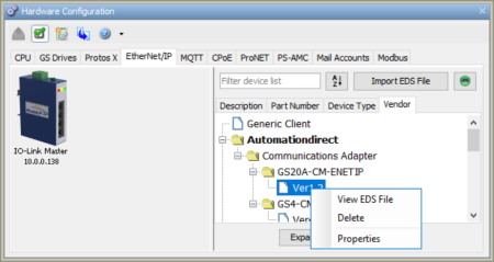
The EDS Library comes pre-populated with AutomationDirect EtherNet/IP Adapter devices. The EDS library is organized into 4 tabs - Vendor, Part Number, Description, and Device Type - and every EDS file in the library is searchable. Each tab organizes the EDS files by a specific field and searching within that tab uses the criteria of that tab / view.
The Vendor tab organizes the
EDS files first by Vendor, then by Device Type,
then by Part Number.
The Part Number tab organizes the EDS files by Part Number only.
The Description tab organizes the EDS files first by Description, then by Part Number.
The Device Type tab organizes the EDS files first by Device Type, then by Part Number:
Each tab is also sortable alphabetically (A-Z or Z-A) by the first level of organization.
The buttons at the bottom of the EDS library window allow the user to expand All of the folders or collapse ALL of the folders.
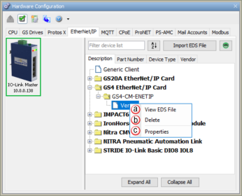
Note: If EIP Clients have already been configured, deleting an EDS file will NOT affect those EIP Clients.
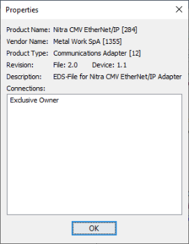
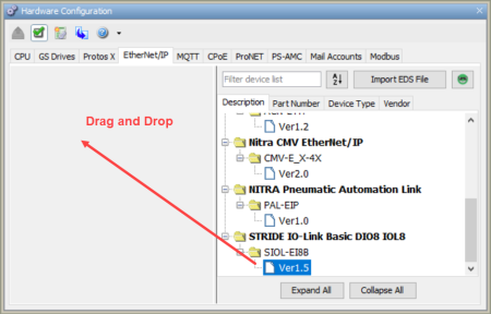
Drag and drop a device from the EtherNet/IP Device list to the EtherNet/IP Client device pane, or double left-click imported device to open the Properties window.
Note: For more information on Device Properties please refer to Ethernet IP/Scanner Configuration.
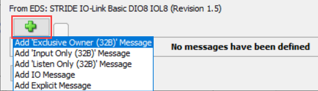
Imported connection(s) will be shown by clicking on the Add I/O Message/Explicit Message.
Note: EDS-specific imported items will be grayed out if not allowed to be modified by the user.
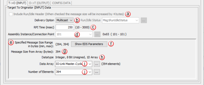
Run/Idle Header & Status: Some adapter devices support run/idle status for the T > O direction. The Include Run/Idle Header check box enables the Run/Idle Status field and increases the message size by 4 bytes.Run/Idle Status is a Boolean tag (On = Run; Off = Idle) indicating the status of the Adapter device.
Delivery Option: Some adapter devices can be configured to Multicast their input data on the network or Unicast their input data back to the Originator (scanner) device. Some devices only support multicasting of input data. In some situations where the Adapter device supports both, it may be desired to have multiple devices consuming this data and it is more efficient to Multicast. Unicast tends to be more ‘quiet’ on most networks.
RPI Time (msec): RPI stands for Requested Packet Interval. This establishes how often the input data (in milliseconds) will be sent back to the Scanner from the Adapter device. The smaller the value configured in this field, the more resource intensive it will be for both devices. See the EtherNet/IP Performance Calculation section for information on RPI restrictions.
Connection Point: This field is where the Connection Point parameter for the desired input data block of the Adapter device is entered. This value is specific for the Adapter and must be ascertained from the manufacturer’s documentation of that device when not using its EDS file. The value is entered in decimal format. There is a hexadecimal representation to the right of the entry field for convenience as many devices specify this parameter in that format.
Specified Message Range: Displays Minimum and Maximum Message Size Range in bytes.
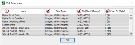
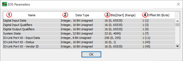
Show EDS Parameters: Provides Data Types, Bit Range & Offset (Bit) Bytes specified by EDS file.
Note: A message is displayed if no data types were defined in the EDS file.
Note: The data type may have been converted to a compatible data type during the import, if the original data type was unsupported by the software.
Note: Some EDS files may not contain [Start] or (Range) elements.
Message Size (bytes): This is a read-only field that displays the size of the data configured by the specified array data type and the Number of Elements field in bytes.
Datatype: This is a read-only field that displays the data type of the selected Data Array. This helps to determine the size of the input data that needs to be configured in order to match the Adapter configuration.
Data Array: The array specified in this field will hold the input data received from the Adapter device. The size of the array must be sufficient to support the specified Number of Elements being requested. If the Number of Elements requested exceeds the array size, a warning will be given to correct this. Only single dimension arrays can be specified for this field.
Number of Elements: This is an entry field to specify the number of array elements that will hold the input data returned from the Adapter device. In Productivity Suite versions 4.1 and later, this can be an integer or an integer tag.
Note: Element byte count must fall within the Minimum and Maximum Message size.
Note: EDS-specific imported items will be grayed out (inhibited) if not allowed to be modified by the user.”
Note: A message is displayed if no data types were defined in the EDS file.
- Name: Name provided by EDS for each line item.
- Data Type: Data type specified by EDS file for each line item.
Note: The data type may have been converted to a compatible data type during the import, if the original data type was unsupported by the software.
- Bits [Start] (Range):
- Bits = Total bits used by specific line item
- Start = Number for starting bit within the byte.
- Range = Minimum & Maximum values allowed. (Min, Max)
Note: Some EDS files may not contain [Start] or (Range) elements.
- Offset Bit (Byte): Bit and byte offset value for each line item.
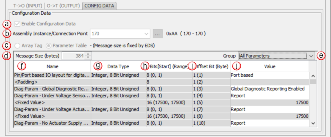
Note: EDS-specific imported items will be grayed out if not allowed to be modified by the user.
Note: Some EDS files may not contain [Start] or (Range) elements.
Right click on an EtherNet/IP imported device to show additional options.