Topic: P251

P3-RX Module Configuration

Description

The P3-RX module (for use with the P3-550(E) CPUs only) is configured using the setup tools found in the Hardware Configuration window.
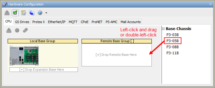
  1. Configure the CPU for a Remote I/O application by left-clicking the desired Base Chassis size from the Components List and dragging it over to the [+] Drop Remote Base Here place holder as seen below.

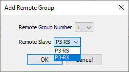
  1. The Add Remote Base Group window will now open. Click on the down arrow and assign a Remote Base Group Number (1-99) to the Remote Base Group. Also, select the P3-RX option from the CPU drop down.

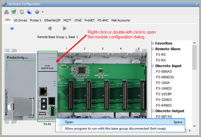
  1. Now that the Remote Base Group is selectable, double-click the Group to open an exploded view of the Remote Group.
  2. Double-click the P3-RX module from this window (below) to open the P3-RX Configuration dialog, which is explained in detail in the following section.

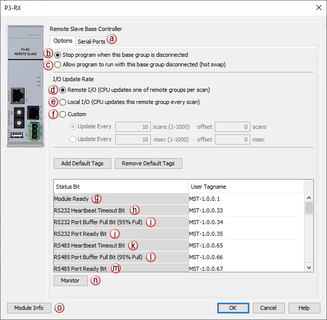
Options Tab Configuration

  1. Serial Ports Tab: Click on this Tab to go to the Serial Ports Configuration dialog.
  2. Stop program when this base group is disconnected: Enabling causes the CPU to treat the loss of communication with this Base Group as a critical error.  The critical error will force the CPU into stop mode.  This is the default setting.
  3. Allow program to run with this base group disconnected (hot swap): Enabling causes the CPU to treat the loss of communication with this Base Group as a non-critical error.  Since the error is non-critical it will not force the CPU into stop mode.  (All I/O Modules in the Base Group must have No Verification selected for the loss of communication with the Base Group to be treated as non-critical error by the CPU.)  In this case, the CPU will do the following:
  1. Remote I/O: This option will set this Remote I/O base to be updated sequentially, asynchronously to the CPU scan. Please refer to the Scan Interval and Use of the Maximum Scan Interval Tag topic for further reference.
  2. Local I/O: This option sets this Remote I/O base to be updated every scan as Local I/O, synchronous to the CPU scan.
  3. Custom: this Remote I/O base can be set to update asynchronously to the CPU scan by either:

Note: Remote HSO and HSI modules and AMC modules are not affected by the Custom setting but are updated every scan. All other I/O modules are updated per the Custom settings.

  1. Module Ready Bit: This Bit will be high when communication is good between the or P3-RX and the P3-550. If communication is lost for any reason, this bit will go low.

    Note: Firmware 1.1.13.x is required to use the Module Ready Bit feature.

  1. RS-232 Heartbeat Timeout Bit: Allows the ladder logic in the CPU to know if a device has stopped communicating to the P3-RX.  The RS-232 Heartbeat Timeout Bit will become true if the RS-232 Comm Heartbeat Value of the Serial Ports configuration is exceeded. The CPU will start a timer between each communication packet coming into the P3-RX.  If a communication packet fails to be received by the P3-RX within the specified time period, the bit will be enabled.
  2. RS-232 Port Buffer Full Bit (95% Full):  A Boolean Tag can be assigned to this field and then used in the ladder code to indicate when communications are almost maxed out on this Port.  When the Port becomes 95% full, the Bit becomes true (value of 1).
  3. RS232 Port Ready Bit: Indicates when the RS-232 Port is ready to be used for to other devices.
    • If the P3-RX is selected as Do not Detect if the Remote Base Group is Disconnected, then the RS-232 Port Ready Bit will be false until the P3-RX is fully booted up and in run.
    • The RS-232 Port Ready Bit will become momentarily false during a stop mode transfer using the programing software.
    • If communication is lost with the P3-RX, the CPU will reset all MST bits associated with that Remote Group.
  1. RS-485 Heartbeat Timeout Bit: Allows the ladder logic in the CPU to know if a device has stopped communicating to the P3-RX.  The RS-485 Heartbeat Timeout Bit will become True if the RS-485 Comm Heartbeat Value of the Serial Ports configuration is exceeded. The CPU will start a timer between each communication packet coming into the P3-RX.  If a communication packet fails to be received by the P3-RX within the specified time period, the Bit will be enabled.
  2. RS-485 Port Buffer Full Bit (95%):  A Boolean Tag can be assigned to this field and then used in the ladder code to indicate when communications are almost maxed out on this Port.  When the Port becomes 95% full, the Bit becomes True (value of 1).

Note: MST bits correlating to any Buffer Full Bit (95% Full) correspond to the queue of instruction data that was executed but is still waiting to be transmitted out of a port. Each Serial port can buffer 100 instructions, and the local Ethernet port can buffer 1000 instructions. The 95% Bit is not related to the number of bytes waiting, but instead to the number of instructions that have data waiting.

Instructions which use the Port Buffer Output Queues: MRX/MWX, RX/WX, GSR/GSW, DWX,AOUT, CPO
  1. RS485 Port Ready Bit: Indicates when the RS-485 Port is ready to be used for communications to other devices.
    • If the P3-RX is selected as Do not Detect if the Remote Base Group is Disconnected, then the RS-485 Port Ready Bit will be false until the P3-RX is fully booted up and in run.
    • The RS-485 Port Ready Bit will become momentarily false during a stop mode transfer using the programing software.
    • If communication is lost with the P3-RX, the CPU will reset all MST bits associated with that Remote Group.
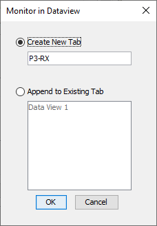
  1. Monitor: Displays the window shown below with options for adding tags to Data View.

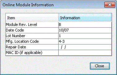
  1. Module Info: Click on this button to open a window that displays information about the specific Module.  A sample of theOnline Module Informationis shown below.


Serial Ports Configuration

There are two Serial Ports on the P3-RX Modules.  There is an RS-232 Port with an RJ-12 connector and a 2-wire RS-485 Port with a removable three pin terminal block.  Both Ports are capable of Modbus RTU Client (device that initiates communications requests) and Server (device that responds to communications requests) communications.  They are also capable of ASCII outgoing strings and incoming strings.


When the Serial Ports Tab is selected, the Serial Ports settings are displayed as shown below.
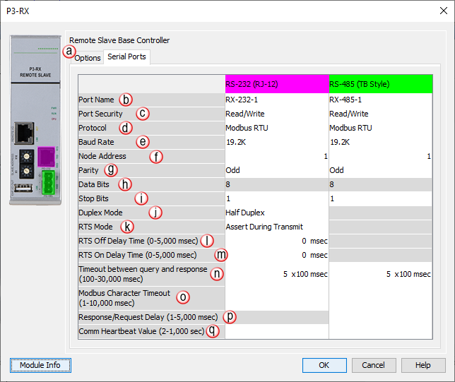
  1. Options Tab: Click on this Tab to go to the Options dialog.
  2. Port Name: Allows the entry of a unique Name for the RS-232 and RS-485 Ports.  This name is referenced inside of the Communications instructions (MRX, MWX, RX, WX) and ASCII instructions (AIN, AOUT, CPO, CPI) to select the Port to send or receive the request.
  3. Port Security: Can be used as a simple Securitymeasure to prevent Modbus RTU write requests from being accepted by the P3-RX.  To allowReads and Writes, selectRead/Write.
  4. Protocol: Determines whether the Port is used for Modbus RTU communications, sending or receiving ASCII Strings or performing the Custom Protocol function.
  5. Baud Rate: Choose from a drop-down list of available Baud Rates (1200, 2400, 9600, 19200, 33600, 38400, 57600, and 115000). All devices communicating on the network must be set to the same Baud Rate.
  6. Node Address: This field can be set from 1 to 247 and is used to uniquely identify the CPU on the network, only when the CPU is a Modbus RTU Server device. This setting is sometimes referred to as a Station Address.
  7. Parity: Used for simple, low-level Error Detection. All devices on the network must be at the same Parity setting. Valid selections are None, Even, and Odd.
  8. Data Bits: Determines whether the communications packet uses Seven Data Bits or Eight Data Bits.  Eight Data Bits is the only valid selection for Modbus RTU.  Either Seven or Eight Data Bits can be selected when using ASCII communications.  Set this field to match the device that is connected to the P3-RX.
  9. Stop Bits: Determines whether the communications packet uses One or Two Stop Bits.  Set this field to match the device that is connected to the P3-RX.
  1. Duplex Mode: In ASCII/Custom Protocol mode, Half Duplex or Full Duplex can be chosen.
  1. Half Duplex: When selected, the Serial Port can either transmit or receive, but not both at the same time.
  2. Full Duplex: When selected, allows the Serial Port to transmit and receive simultaneously (Only available in ASCII/Custom Protocol).
  1. RTS Mode: Set the RTS mode to control the Request To Send signal out of the Serial port.


  1. RTS Off Delay Time (RS-232 Only): The amount of Time between the end of the data transmission to when the RTS signal is turned off.  The diagram below illustrates this.  This setting may be needed when using media converters (RS-232 to RS-422/485 converters) and/or radio modems.  A delay may be needed at the end of the data transmission for processing time in the device.

  1. RTS On Delay Time (RS-232 Only): The amount of Time between when the RTS Signal is turned ON and the data transmission begins.  The diagram below illustrates this. This setting may be needed when using media converters (RS-232 to RS-485 converters) and/or radio modems.  A delay may be needed after the assertion of the RTS Signal and when the data transmission begins for processing time in the device.


  1. Timeout Between Query and Response: The allowable Time between when a query is sent from the P3-RX (via a Communication instruction, such as an MRX, MWX, RX, or WX) and when a Response from that device is Received, before a Timeout Error will occur for the given instruction.  Each instruction has a Timeout Status bit that can be assigned to it.

  1. Modbus Character Timeout: The Time between two bytes (or characters) within a given Modbus Message.  The Modbus RTU specification states that this time must be no more than 1.5 Character Times (real time based on Baud Rate). Sometimes delays do occur between bytes when using radio modems, media converters, etc.  This setting allows some tolerance in these situations for the incoming Modbus Messages in the P3-RX. The P3-RX will wait for the amount of time specified in this field before discarding the incomplete packet. If the P3-RX does not receive the remainder of the Message within the specified Time Frame, it will discard the first portion of the Message and wait for a new Message.

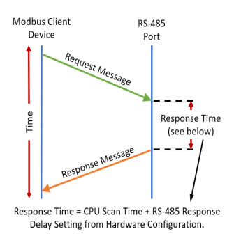
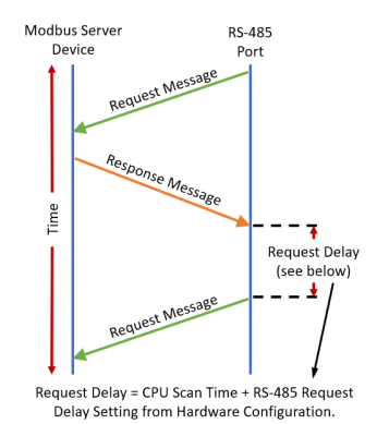
  1. Response/Request Delay (RS-485 Only):  Used when the CPU is a Modbus RTU Server or Client on the RS-485 Port. The total Response Time can be up to the Total CPU Scan Time + the Value specified in this field. When using 2-wire RS-485 communications, sometimes Echoes can occur since both devices use the same differential signal pair to send and receive.

  1. Comm Heartbeat Value: If a value is placed in this field, a timer will start between each communication packet coming in to the P3-RX.  If a communication packet fails to be received by the P3-RX within the specified Time period, the System Bit RS-232 Heartbeat Timeout Bit or RS-485 Heartbeat Timeout Bit will become true.