|
|
Topic: P246 |
High Speed Module Tester Utility |
|
|
|
Topic: P246 |
High Speed Module Tester Utility |
|
The High Speed Module Tester is a software utility that allows a user to test the Productivity Series High-Speed Output and Advanced Motion Control modules inputs and outputs. It is highly recommended to simulate your HSO/AMC functions before attempting to control the module from your CPU program. This utility can be useful with debugging, confirming field wiring and verifying external device operation.
The High Speed Module Tester can be accessed using three methods:
Method 1
Select the HS Testing icon
from the Monitor Toolbar.
Method 2
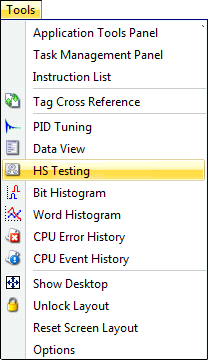
Select the HS Testing menu item from the Tools Menu of the Main Menu.

Method 3
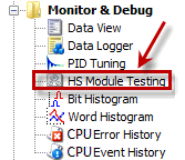
Select HS Testing from the Monitor & Debug topics of the Application Tools panel.

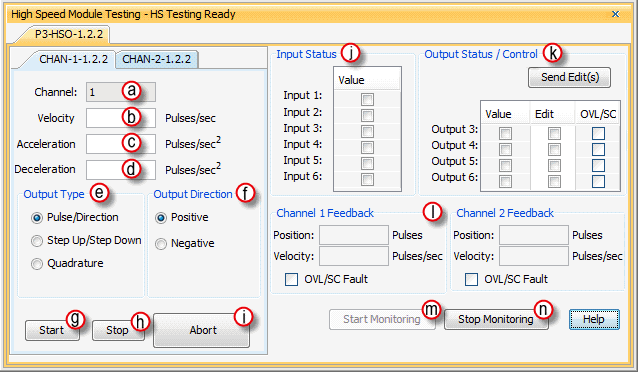
Selecting the High Speed Module Tester using any of the above methods will open the following window:

The High Speed Tester window provides the following:
Channel/Axis: Indicates the channel number selected for testing.
Velocity: A value that specifies the desired velocity to accelerate to. The Velocity value must be in the range of 1 to 1e6.
Acceleration: A value that specifies the rate of acceleration while ramping to the target velocity.
The Acceleration value must be within the range of 1 to 100e6.
Deceleration: A value that specifies the rate of deceleration while ramping to a stop. The Decelerationvalue must be within the range of 1 to 100e6.
Output Type:(HSO module)
Pulse/Direction: This selection configures the module to generate the pulse train on Output A of the channel and the direction is established on Output B of the channel. When the logic tells the module to change directions, Output B will toggle from low to high and vice versa.
Step Up/Step Down: When this selection is specified, the pulse train is generated on Output A when a positive direction has been specified and on Output B when a negative direction has been specified.
Quadrature: When this selection is specified, the pulse train output is generated on Output A and B and the signals are offset by a ½ cycle. Direction changes from the logic cause the offset to change from one output to the other.
Output Direction: Select a travel direction for the output.
Start: Selecting Start will begin the testing process. The output will accelerate at the desired rate to the desired velocity in the specified direction.
Stop: Selecting Stop will stop the testing process causing the output to decelerate to a stop at the specific rate.
Abort: Selecting Abort will stop the testing process immediately.
Input Status: Select to provide status indications of discrete inputs.
Output Status/Control:
Allows user to manually turn on the desired output. Indications are
provided for outputs that have Overload/Short Circuit conditions. To
change an output's state, check the box in the
Edit column and press
Send Edits.
Channel 1 and Channel 2 Feedback:
Position: References the channel's current position count.
Velocity: References the channel's current velocity.
OVL/SC: Indicates if an output has an Overload/Short Circuit condition.
Start Monitoring: Enables the Monitor functionality of the utility, allowing user input.
For quick testing of the HSO/AMC module, use the following steps:
Note: For testing an HSO/AMC module, it is not necessary to download the hardware configuration to the CPU.
Note: To enable the HS Testing Utility, the Run/Stop switch on the CPU must be in stop or select stop mode from the GUI.
Note: Output, physical and position limits set in the hardware configuration are not active while using this utility.