|
|
Topic: P229 |
P3-RS Module Configuration |
|
|
|
Topic: P229 |
P3-RS Module Configuration |
|
The P3-RS module is configured using the setup tools found in the Hardware Configuration window.

- The CPU will log the error.
- The CPU will use the last data received before the mismatch in the execution of ladder logic. Once the mismatch no longer exists and current data is available from the Base Group, the CPU will switch over to using current data.
Remote I/O: This option will set this Remote I/O base to be updated sequentially, asynchronously to the CPU scan. Please refer to the Scan Interval and Use of the Maximum Scan Interval Tag topic for further reference.
- # of scans with offset (scan based)
- msec with offset (time based)
This bit only applies when the RX ports are being used as a slave device and only monitors the time between the communications from the master device
Note: Firmware 1.1.13.x is required to use the Module Ready Bit feature.
Note: MST bits correlating to any Buffer Full Bit (95% Full) correspond to the queue of instruction data that was executed but is still waiting to be transmitted out of a port. Each Serial port can buffer 100 instructions, and the local Ethernet port can buffer 1000 instructions. The 95% Bit is not related to the number of bytes waiting, but instead to the number of instructions that have data waiting.
Instructions which use the Port Buffer Output Queues: MRX/MWX, RX/WX, GSR/GSW, DWX,AOUT, CPO
- If the P3-RS is selected as Do not Detect if the Remote Base Group is Disconnected, then the RS-485 Port Ready Bit will be false until the P3-RS is fully booted up and in run.
- The RS-485 Port Ready Bit will become momentarily false during a stop mode transfer using the programing software.
- If communication is lost with the P3-RS, the CPU will reset all MST bits associated with that Remote Group.
There are two Serial Ports on the P3-RS Modules. There is an RS-232 Port with an RJ-12 connector and a 2-wire RS-485 Port with a removable three point terminal block. Both Ports are capable of Modbus RTU Client (device that initiates communications requests) and Server (device that responds to communications requests) communications. They are also capable of ASCII outgoing strings and incoming strings.
When the Serial Ports Tab is selected, the Serial Ports settings are displayed as shown below.
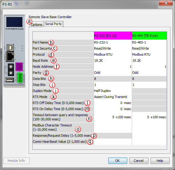
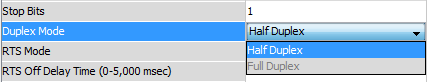
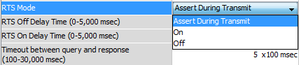
- Assert During Transmit: Make the RTS signal turn ON in the time between the RTS ON delay and RTS OFF delay. (Only available in Half Duplex Mode)

- On: Make the RTS signal ON all the time.

- Off: Make the RTS signal OFF all the time.


The total Response Time can be up to the Total CPU Scan Time + the Value specified in this field. When using 2-wire RS-485 communications, sometimes Echoes can occur since both devices use the same differential signal pair to send and receive.
- If acting as a Server, upon receiving a Modbus Request, the CPU will wait for the time period specified in this field before sending a Response. This can be used with slow clients that need extra time to change from sending to receiving.
- If acting as a Client, after receiving a Modbus Response, the CPU will wait for the time period specified in this field before sending another Request. This can be used to delay request messages in order to give extra time for slow server devices.