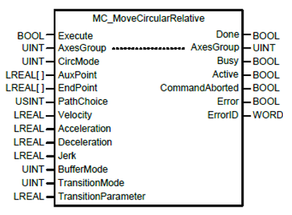
Incremental position circular interpolation operation with MC_MoveCircularRelative
MC_MoveCircularRelative gives a relative circular interpolation movement command to an axis group. When this motion function block starts, each axis performs circular trajectory interpolation control referring to the auxiliary point input, and the movement direction is determined by PathChoice input. If PathChoice input is set to 0, circular interpolation is operated in a clockwise direction, and if it is set to 1, circular interpolation is operated in a counter-clockwise direction. Specify the relative position of the auxiliary point used when doing circular interpolation of each axis in AuxPoint and EndPoint input arrays.
-
The array data location corresponds to the Axis ID in the axis group (for example, AuxPoint[0] is for Axis ID 01 in the group).
-
A maximum of 3 axes can be used in a circular interpolation move.
-
Refer to Chapter 8.2.8 of the XMC manual for more information about circular interpolation control.
-
LS_Connect, MC_GroupEnable and MC_GroupPower (or equivalent) must be executed before this function block.
-
The examples in this topic can be found in the XMC_AxisGroup_FBs.zip downloadable from Example Applications.
| Element Name | Element Type | Description |
|---|---|---|
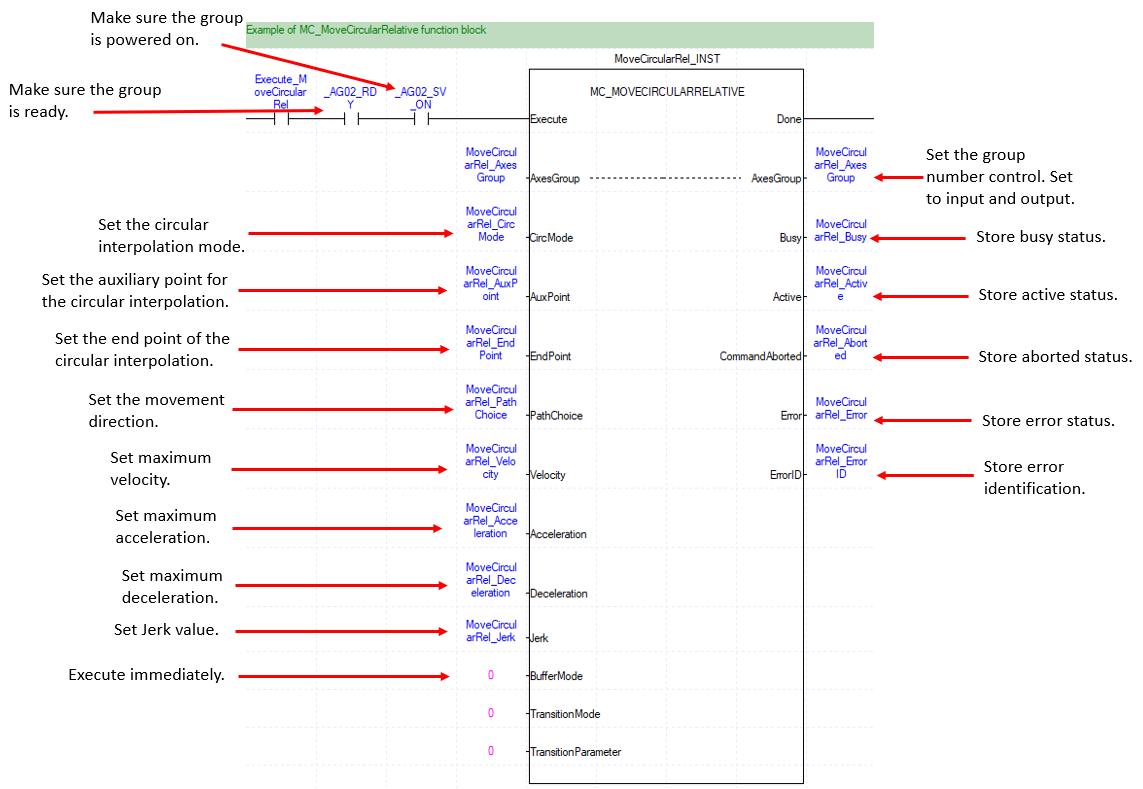
| Execute | Input | Edge detected request to execute the function block. |
| AxesGroup | Input/Output | Set the group to execute the function block on. Group number 1-16. This must be an UINT variable. |
| CircMode | Input |
Specify the circular interpolation method. See CircMode Explanation for more information.
|
| AuxPoint | Input | Specify the position of the auxiliary point in a relative coordinate based on the starting position. |
| EndPoint | Input | Set the circular end point as a relative coordinate based on the starting position. |
| PathChoice | Input |
Circular route selection.
|
| Velocity | Input | Specify the maximum speed of the route. |
| Acceleration | Input | Specify the maximum acceleration. |
| Deceleration | Input | Specify the maximum deceleration. |
| Jerk | Input | Specify the change in rate of acceleration/deceleration. |
| BufferMode | Input | Specify the sequential operation setting. See Buffer Mode table below. |
| TransitionMode | Input | Not Used. |
| TransitionParameter | Input | Not Used. |
| Done | Output | Indicates the completion of the function block execution. |
| Busy | Output | Indicates the function block is in operation. |
| Active | Output | Indicates the function block is controlling the group. |
| CommandAborted | Output | Indicates the function block has been aborted. |
| Error | Output | Indicates whether an error occurs or not. |
| ErrorID | Output | Indicates the error number if an error is present. |
BufferMode Table
Sections 6.1.4 and 8.2.10 of the XMC user manual provide more information about buffer modes.
| Value | Buffer Mode | Description |
|---|---|---|
| 0 | Aborting | Abort previous command and execute the command immediately. |
| 1 | Buffered | Execute the command after previous command is completed. |
| 2 | BlendingLow | The new command is blended into a previously executed command using the lower velocity value when comparing the previous command and new command. |
| 3 | BlendingPrevious | The new command is blended into a previous command using the velocity of the previous command. |
| 4 | BlendingNext | The new command is blended into a previous command using the velocity from the new command. |
| 5 | BlendingHigh | The new command is blended into a previous command using the higher velocity value when comparing the previous command and new command. |
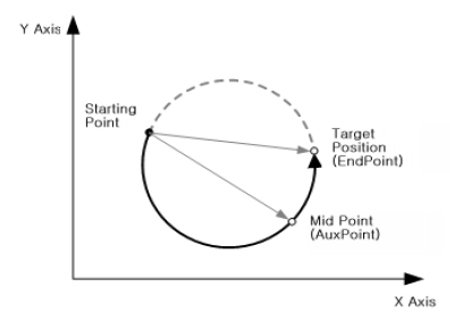
Circular Interpolation Using Midpoint Specification (CircMode = 0)
In this method, the operation starts at the current position and it does circular interpolation through the specified position of the central point to the target position.
In the figure below, the current position corresponds to the axes group coordinate at the start of the command, the midpoint corresponds to the coordinate input for the AuxPoint, and the target position corresponds to the relative coordinate input for the EndPoint.
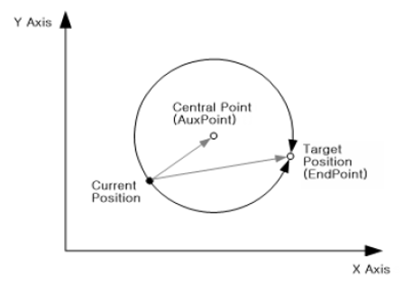
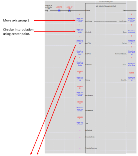
Circular Interpolation Using Center Point Specification (CircMode = 1)
In this method, the operation starts at the current position, and it does circular interpolation to the target position along the circular path, which has a radius of the distance to the specified central position.
In the figure below, the current position corresponds to the axes group coordinate at the start of the command, the center point corresponds to the coordinate input for the AuxPoint, and the target position corresponds to the relative coordinate input for the EndPoint.
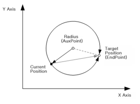
Circular Interpolation using Radius Specification (CircMode = 2)
In this method, the operation starts at the current position, and it does circular interpolation to the target position along the circular path which has a radius of the value specified in the radius.
In the figure below, the current position corresponds to the axes group coordinate at the start of the command, the diameter corresponds to the X coordinate input for the AuxPoint, and the target position corresponds to the relative coordinate input for the EndPoint.
-
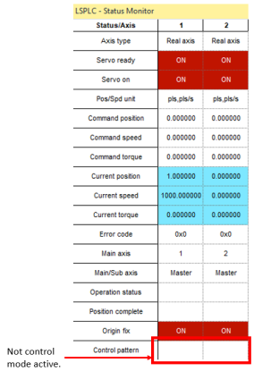
Axis Group 2 contains Axis 01 and Axis 02 in it.
-
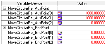
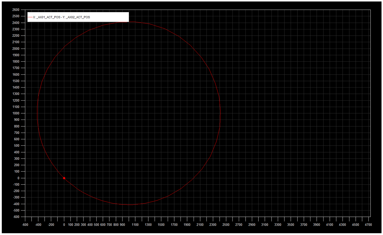
Starting position is (0.0, 0.0)
-
Ending Position (0.0, 0.0)
AuxPoint Array:
-
[0] – Axis 1 center point
-
[1] – Axis 2 center point
EndPoint Array:
-
[0] – Axis 1 end position
-
[1] - Axis 2 end position
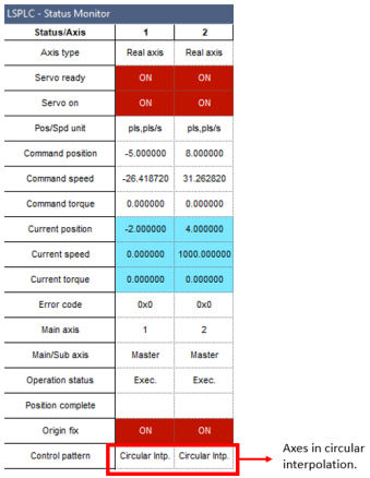
Before MC_MoveCircularRelative
During MC_MoveCircularRelative
LM714