Connect to GS20 with ModbusTCP

This procedure will walk through setting up read/write communications between the LS XEM CPU and GS20 AC Drive using the Modbus TCP protocol. Modbus TCP communications is set through the Project configuration. No ladder programming is required for communications.

Note: A GS20A-CM-ENETIP module is required for the GS20 AC drive to use Modbus TCP.

An example program can be found in GS20_ModbusTCP on the Example Applications page.

Step Action
1

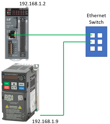
Connect the XEM processor and Drive via Ethernet.

2

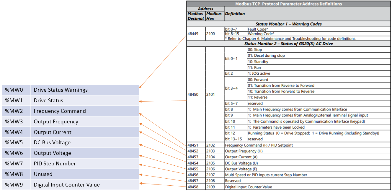
Setup PLC Direct Memory Addresses for Drive Status Information and determine the PLC internal memory addresses for use.

3

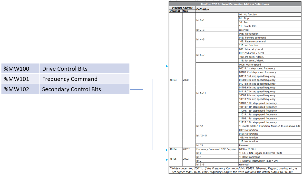
Setup PLC Direct Memory Addresses for Drive Control and determine the PLC internal memory addresses for use.

4

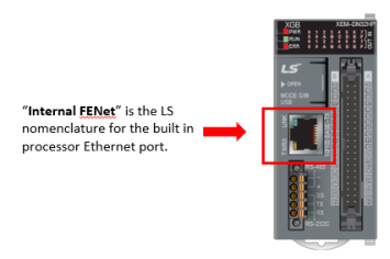
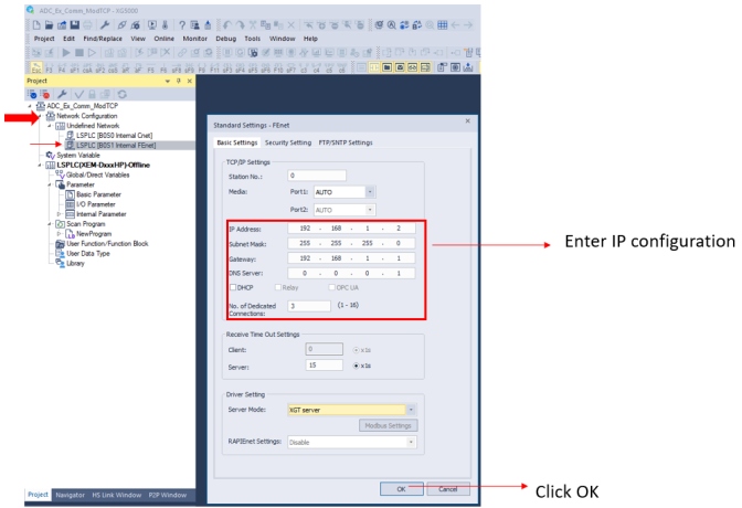
Set the Ethernet Address in the LS XEM processor.

  1. In the Project window, open Network Configuration and double-click LS PLC[B0S1 Internal FE net].

5

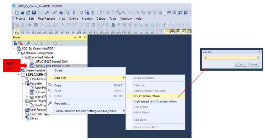
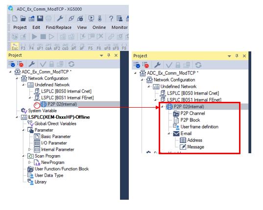
Add ModbusTCP communications configuration.

  1. Right-click Internal FENet.

  2. Choose Add Item – P2P communication.

  1. Select 02 and click OK. This will create the P2P 02 configuration selections in the Project tree.

6

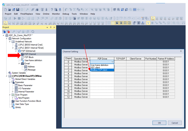
Set up the Channel for the Modbus TCP comms to the VFD.

  1. Double-click P2P Channel and the Channel setting window will open. From the drop down , choose Modbus TCP Client and press Enter.

  2. Enter the IP address of the GS20 AC drive. Select OK.

  3. The channel is now available for selection in the P2P Block window.

7

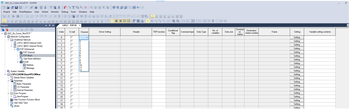
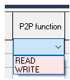
Use the P2P Block configuration to set the Read/Write blocks to the VFD.

  1. Double-click P2P Block and the LSPLC P2P 02 Block configuration window will open. From the drop down, choose Channel 0 (created in previous step). Press Enter.

  2. Driver Setting is automatically set to Modbus TCP Client based on the Channel 0 setup. The row will show up pink until the configuration is complete. After all the fields are completed, the red highlight will be removed, indicating the configuration is complete and accurate.

8

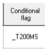
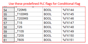
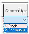
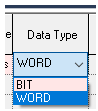
Set the P2P Block configuration fields

  1. Choose Modbus TCP Read or Write.

  2. Enter a variable tagname in Conditional flag to determine the communication rate of the block.

    We recommend using the preconfigured flags built into the processor. This example will use _T200MS to communicate every 200 milliseconds.

  3. Set to Single to only send 1 unit of the data type. Set to Continuous to send multiple units. Define # units in Data Size field.

  4. Select WORD Data type.

  5. If you selected 2. Continuous for the Command type, the Data size can be entered. This is the number of units to read (depending on data type selection), Max 200.

9

Set the Modbus TCP registers to Read.
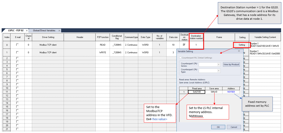
  1. Click Setting. The Variable Setting box will appear.

  2. Set the Read Area to the GS20 ModbusTCP register.

  3. Set the Save Area to the LS PLC internal register.

  4. Select OK.

10

Complete the Modbus TCP registers Read and Write configuration.

If all data is entered correctly the row will be Grey/White. If row is Red, recheck all fields.

Note: Direct Memory Tags are required for Modbus TCP data ( M or W type is recommended)

11

Add Descriptions to PLC memory address (optional). For ease of identifying the registers only.

  1. Open Global/Direct Variables window.

  2. Choose the Direct Variable Comment tab.

  3. Type the variable in the search window.

  4. Enter description in the Comment field.

12

Write the Program to the PLC.

  1. Compile, verify no errors and save the program.

Note: at least 1 scan program must be configured or an error will occur.

  1. Connect to the PLC.

  2. Write the program to the PLC.

  3. Verify that P2P 02 is enabled.

  4. Run the program and Communications will be active.


LP210