Digital Output Module Configuration
Adding a digital output module to XG5000 project.
| Step | Action |
|---|---|
| 1 |
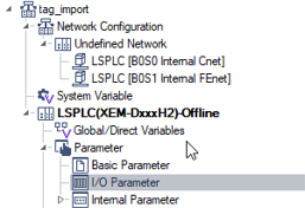
Open I/O Parameter in the XG5000 project.
|
| 2 |
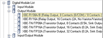
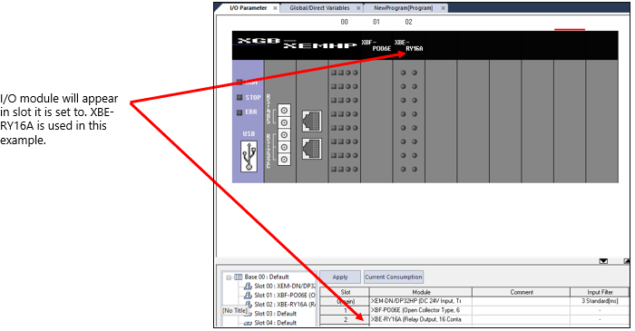
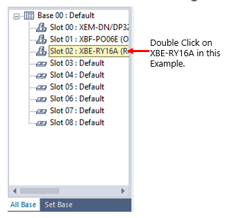
Insert the Digital I/O module in the slot it will be on the physical PLC rack. It is in Digital Module List.
|
| 3 | Direct Variables are assigned to the module based on slot number. See LP003B for information on Digital I/O addressing. |
| Optional | Refer to Base PLC Variables: Create, Import, and Export to Create Base PLC I/O tags. You can optionally create variables to alias the digital inputs. |
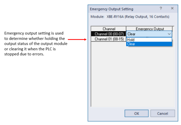
Open Emergency Output Setting screen in the I/O Parameter window. An input filter value can be set from this screen.
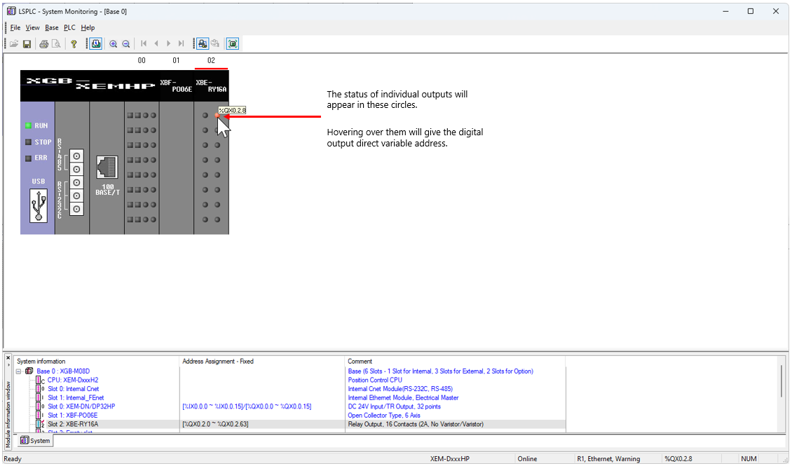
Using the System Monitoring Screen allows user to see the status of a digital output module.
| Step | Action |
|---|---|
| 1 | Open Monitor menu è System Monitoring. |
| 2 |
See status of digital outputs (below example is XBE-RY16A).
|
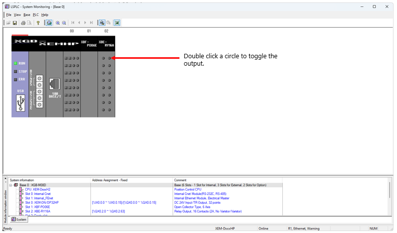
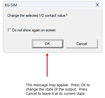
Using the System Monitoring Screen allows you to also manually control a digital output. Just double-click on the output that should be changed.
LP105-2