|
|
|
Topic: CL295 |
Velocity Move for PTO Axis |
|
|
The Velocity Move Instruction is used to continuously control the Axis by the Target Velocity (ignoring the current position). The Velocity can be any value between +/- of the configured Maximum Velocity. A velocity of Zero is also valid and will pause the Axis. The change in Velocity is affected by four settings: Minimum Velocity ( set in Pulse Train Output configuration), Acceleration, Deceleration, and the S-Curve Option. The Target Velocity can be changed at any time during the Move.
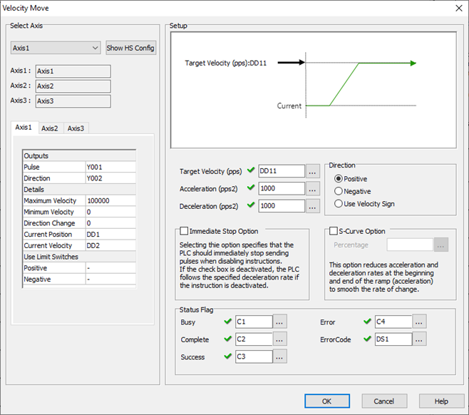
1 Select Axis: The PTO Axis must be created in the High Speed I/O Setup before placing the Velocity Move Instruction into ladder.
2 Axis Names: These are the Axis names as defined in the High Speed I/O Setup.
3 Axis Settings: This is a read-only view of the Axis settings from the High Speed I/O Setup.
4 Target Velocity: Constant or DD Register. The Axis will continuously follow this Velocity using the settings as configured by the rules configured for: Minimum Velocity, Maximum Velocity, Acceleration, Deceleration, and the S-Curve Option.
5 Acceleration: Constant or DD Register. The change of rate value used only during Acceleration (Pulses Per Second Squared).
6 Deceleration: Constant or DD Register. The change of rate value used only during Deceleration. (Pulses Per Second Squared)
7 Direction: These settings control how the value in the Target Velocity will be interpreted.
Positive: Ignore the Target Velocity Sign and always travel in the Positive Direction.
Negative: Ignore the Target Velocity Sign and always travel in the Negative Direction.
Use Velocity Sign: Travel in the Positive Direction for Positive Velocities, Travel in the Negative Direction for Negative Velocities.
8 Immediate Stop Option: The behavior of an Aborted Move can be chosen.
Enabled: Selecting this option specifies that the PLC should immediately stop sending pulses when disabling instructions. This will abort the Move abruptly and likely lose the Axis Home reference if traveling at high speeds.
Disabled: If the check box is deactivated, the PLC follows the specified deceleration rate if the instruction is deactivated. The Axis will continue to follow its configured rules until reaching zero velocity.
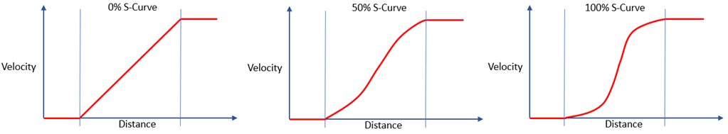
9 S-Curve Option: This option smooths the velocity change to create non-linear transitions during Acceleration and Deceleration. The valid range is 1 to 100%. Increasing the S-Curve Percentage does not increase the time during the Velocity change because the rate of change is increased. At 100% S-Curve Percentage, the maximum Rate of Change will be 200% of the specified Acceleration or Deceleration values. The limits of the actual system must be considered, and these parameters adjusted to prevent position loss due to inertia or friction loses.
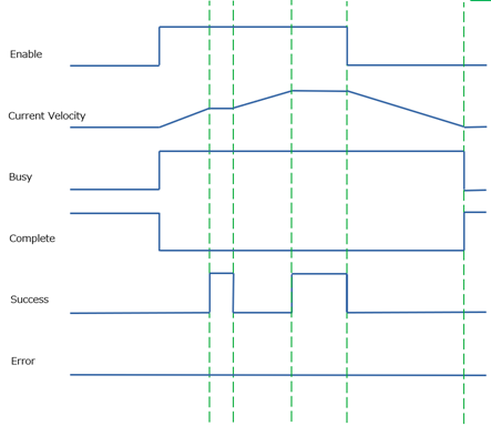
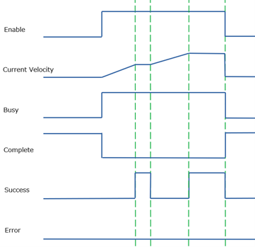
10 Busy: This C bit turns ON while the instruction is in operation and controlling the Axis. Only a single instruction can be in control of each Axis during any moment of time. This bit turns OFF when the instruction is Complete by Success or by Error.
11 Complete: This C bit turns ON when the instruction is Complete by Success or by Error. It stays ON until the instruction is re-enabled.
12 Success: This C bit turns ON to indicate the Axis has matched the commanded Target Velocity. During Acceleration and Deceleration the bit will be OFF. If the Target Velocity is above the Maximum Velocity, the Axis will run at the Maximum Velocity and the Success Flag will not be ON during this situation.
13 Error: This C bit turns ON to indicate a failure of the Instruction or Axis. It stays ON until the instruction is re-enabled. The Value in the Error Code register will indicate the problem.
14 Error Code: Assign a DS or DD register to store the Numeric Error Code.
|
|
Note: The System Bits SC150-SC152 “_PTO_AxisX_Ready_Flag” provide status information. |
|
