AutomationDirect GS Drives Ethernet Setup |
Topic: CM517 |
This GS Drive protocol allows C-more to easily and directly access the drive parameters for viewing and/or adjustment over an Ethernet Connection when used in conjunction with a GS-EDRV module.
C-more Protocol Manager Settings
- Do one of the following:
- Click the Protocol Manager button on the Home tab
— or — - Click the Protocol Manager button on the Setup tab
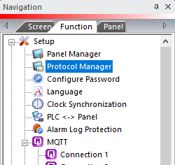
— or — - from the Navigation window, click the Function tab, click Setup and then select Protocol Manager.
- From the Protocol Manager window, click the Device name on the tree to the left.
- The Device Setup window opens.
-
From the PLC Protocol field, click on the down arrow
 and select AutomationDirect GS Drives TCP/IP (GS-EDRV).
When you select a different PLC Protocol than the one currently in use, the warning Message shown below appears.
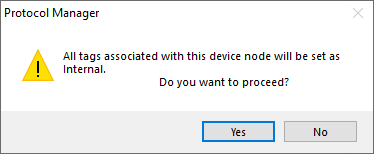
- Click Yes to accept.
Connection Through Another Panel
You can configure this protocol for any PLC supported by C-more panels.
You can connect a C-more panel to other C-more panels on your network via an ethernet connection. This type of connection is also known as a Pass Through Connection.
Go to Connection Through Another Panel (Pass-Through) to learn more about Pass Through and using Connection Through Another Panel.
|
|
Note: To find the IP Address for the GS-EDRV, the NetEdit utility will be required and can be obtained at www.automationdirect.com in the Technical Support Free software download area.After you have downloaded and installed Netedit, open the software and browse the network. You will see the GS-EDRV (as shown in the image below) and can obtain the IP Address and insert this address into the C-more Panel Manager configuration. |
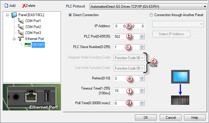
PLC Protocol Settings
a. IP Address
The IP Address of the GS-EDRV.Find it with the NetEdit utility.
b. PLC Port (0-65535)
The destination TCP port number that C-more sends to the GS-EDRV.502 is the standard default. Sometimes this number may need to be adjusted for firewall/router purposes.
c. PLC Slave Number(0-255)
This corresponds with the Unit ID number in the protocol header. You can set this number to any value, as the GS-EDRV will echo the value sent. This field may be implemented in the future for gateway/routing purposes.
d. Register Write Function Code and Coil Write Function Code
These fields are read only and are not accessible.
e. Retries(0-10)
The C-more panel will sends a request to the specified device. If the device does not reply within the specified timeout, the C-more sends the request again. Once the retry count (specified in this field) limit is reached, the C-more panel displays a PLC Timeout error on the screen.
f. Timeout time (1-255)(in 100ms units)
The amount of time (in 100 ms units) that the panel will wait on a reply after sending a request.
g. Poll Time (0-30000 msec)
The amount of time (in milliseconds) that the panel will wait in between each request.
