Omron CS/CJ FINS Ethernet Protocol Setup |
Topic: CM310 |
The following information applies to Omron CS/CJ FINS PLC compatible with C-more Panels using FINSEthernet Protocol. The setup may differ for the CJ series.
The C-more panel is the master by default.
Omron FINS CS/CJ Series Ethernet Setup
This example uses the Omron CX-Programmer PLC Programming Software.
To set up the Omron PLC, do the following:
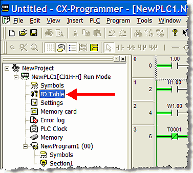
- From the Main GUI screen, select New Project and then NewPLC1 (CJ1H-H Run Mode.
- On the left side window, double-click IO Table as shown on the figure below.
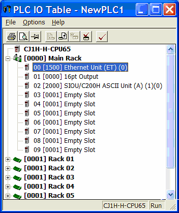
- The PLC IO Table window opens.
- Right click on Ethernet Unit (ET) (0) shown highlighted in the figure below, to bring up the options for the Ethernet Module.
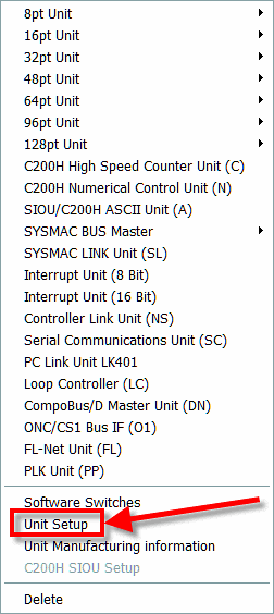
- The drop-down menu shown below opens.
-
Select Unit Setup.
- The Configuration window for the Ethernet Module opens.
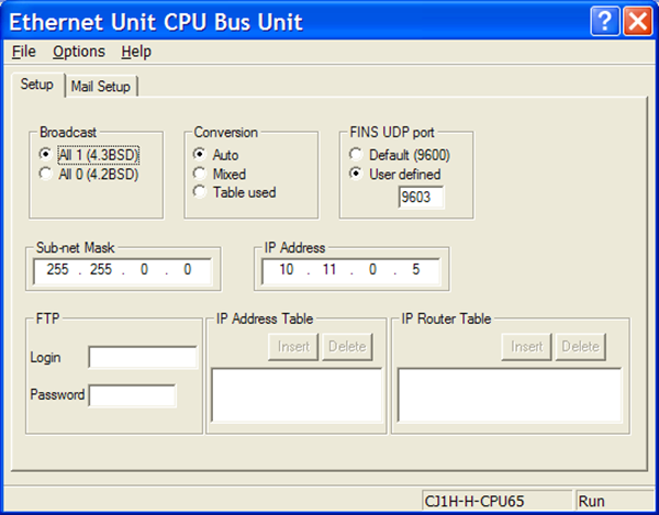
- Complete the fields on the screen using the information in the table below.
| Panel Manager | |
|---|---|
| Field | Description |
| Broadcast | Leave the Broadcast setting as shown above. |
| Conversion | Leave the Conversion setting as shown above. |
| FINS UDP port | Where to find the UDP listening port of the Ethernet Module. This number should match the PLC Port field of the C-more Programming Software Panel Manager window. |
| Sub-net Mask | The Sub-net Mask of the Omron Ethernet Module must match the Subnet Mask (reference the Panel Network - Ethernet Port topic in this Help File or Chapter 5 of User Manual, Page 5-16) of the C-more panel. |
| IP Address: | The IP Address you enter in the Omron CX-Programmer PLC Programming Software must match the IP Address you will enter in the C-more Programming Software Panel Manager window. |
|
|
Note: This is the dialog box to set up the IP Address for the CS1 ETN21 Ethernet Module. Other Omron CS1 and CJ1 Ethernet Modules may have switches to set the IP Address. Refer to Omron documentation for the specific method of setting the IP Address for the module you may have. |
Routing Functions
The Omron FINS Ethernet Protocol also allows for Routing Functions. This allows a Master/Client device to communicate with other devices on other networks through an Omron Ethernet Module. C-moredoes not support this functionality. The C-more FINS Ethernet Protocol is only for communicating directly with an Omron PLC on the local network.
Six fields are used for routing in the Omron FINS Ethernet Protocol header:
- Destination Network Address: C-more always places a value of 0 in this field (local network).
- Destination Node Address: C-more places the value from the Station Number field in the Panel Manager setup.
- Destination Unit Address: C-more always places a value of 0 in this field (CPU Unit Number).
- Source Network Address: C-more always places a value of 0 in this field (local network).
- Source Node Address: C-more places the value from the My Station Number field in the Panel Manager setup.
- Source Unit Address: C-more always places a value of 0 in this field.
The above settings are not accessible in the C-more Programming Software.
C-more Protocol Manager Settings
- Do one of the following:
- Click the Protocol Manager button on the Home tab
— or — - Click the Protocol Manager button on the Setup tab
— or — - from the Navigation window, click the Function tab, click Setup and then select Protocol Manager.
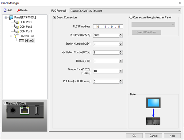
- From the Protocol Manager window, click the Device name on the tree to the left.
- The Device Setup window opens.
- Click on the down arrow
 and select
Omron CS/CJ FINS
Ethernet.
and select
Omron CS/CJ FINS
Ethernet.
When you select a different PLC Protocol than the one currently in use, the warning Message shown below appears.
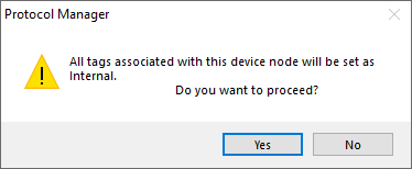
- Click Yes to accept.
- Complete the fields on the screen using the information in the table below.
| Panel Manager | |
|---|---|
| Field |
Description |
| IP Address | Enter the IP Address of the Omron Ethernet Module into this field. Also be sure to match the Subnet Mask of C-more Panel to the Omron Ethernet module Subnet Mask. |
| PLC Port | Enter the FINS UDP Port of the Omron Ethernet Module into this field. |
| Station Number | The Node
Address setting of the Ethernet
Module. This field can be set to either the
actual Node Address
setting of the module
(set by rotary switches on the module
itself), or it can be set to 0. C-moredoes not support this type of communications. The Station Number field and the subsequent My Station Number field are the only to allow C-more a Unique Station Number on the Network. |
| My Station Number | The Node Address setting of C-more. This value must be unique on the Network. Your network conditions may restrict the value, possibly to the host part of the C-more IP address; for example, if the host computer has an IP of nnn.nnn.nnn.123 and the subnet mask is 255.255.255.000, My Station Number should be 123. |
| Retries | This is the number of times that C-more will Retry to send a Message if the request does not receive a reply in the specified Timeout period. Once the Retry count has been reached, C-more will show an error on the screen and begin trying to send messages again. |
| Timeout Time | The amount of time (in 100ms units) that C-more will wait on a reply after sending a request. Once the Timeout Timer expires, it will then retry. |
| Poll Time | The time (in milliseconds) that C-more will wait in between each Message that it sends to a configured device (after the device responds). If this field is set to 0, C-more will send messages as fast as its resources and the selected protocol will allow. |
Connection Through Another Panel
You can configure this protocol for any PLC supported by C-more panels.
You can connect a C-more panel to other C-more panels on your network via an ethernet connection. This type of connection is also known as a Pass Through Connection.
Go to Connection Through Another Panel (Pass-Through) to learn more about Pass Through and using Connection Through Another Panel.
|
|
Note: Power cycle the Omron PLC after changing port settings. |
