AutomationDirect Do-more Serial (Built-in Memory) |
Topic: CM304 |
The following information applies to AutomationDirect Do-more PLC compatible with C-more Panels.
C-more Protocol Manager Settings
- Do one of the following:
- Click the Protocol Manager button on the Home tab
— or — - Click the Protocol Manager button on the Setup tab
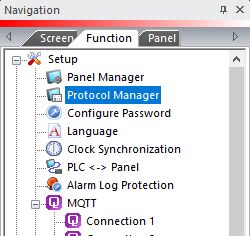
— or — - from the Navigation window, click the Function tab, click Setup and then select Protocol Manager.
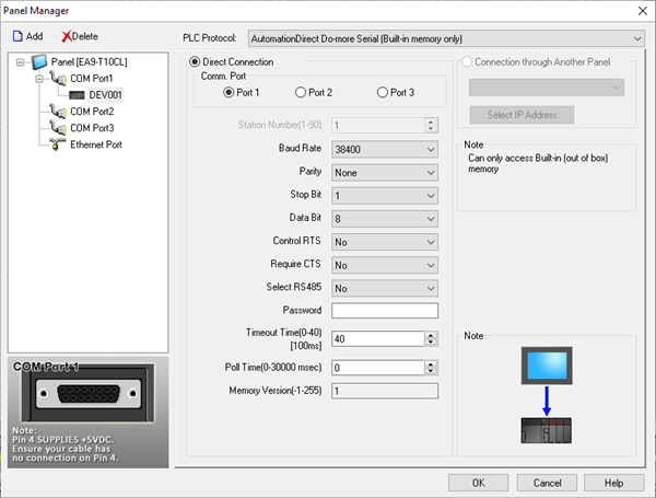
- From the Protocol Manager window, click the Device name on the tree to the left.
- The Device Setup window opens.
-
In the PLC Protocol field, click on the down arrow
 and select AutomationDirect
Do-more Serial.
and select AutomationDirect
Do-more Serial.
When you select a different PLC Protocol than the one currently in use, the warning Message shown below appears.
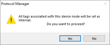
- Click Yes to accept.
Connection Through Another Panel
You can configure this protocol for any PLC supported by C-more panels.
You can connect a C-more panel to other C-more panels on your network via an ethernet connection. This type of connection is also known as a Pass Through Connection.
Go to Connection Through Another Panel (Pass-Through) to learn more about Pass Through and using Connection Through Another Panel.
PLC Protocol Settings
Baud Rate
Match the setting in the Do-more CPU serial port configuration.
Parity
Match the setting in the Do-more CPU serial port configuration.
Stop Bit
Match the setting in the Do-More CPU serial port configuration. This value will most often be set to 1.
Control RTS
Select Yes in this drop-down to asserts the C-More panel RTS signal before every serial transmission for the purpose of using media converters such as FA-ISOCON.
Require CTS
Select Yes in this drop-down If using a modem on the C-more serial port for flow control. Otherwise, leave this setting at No.
Select RS 485
Select Yes in this drop-down if you need 2 wire RS 485 communication. Along with selecting Yes in this field, you must jumper the SD+ and RD+ along with the SD- and RD- pins.
Password
If the Do-more CPU has a password, it will be necessary to enter the password into this field in order to access the PLC.
Timeout time (0-40) (in 100ms units)
The amount of time (in 100 ms units) that the panel will wait on a reply after sending a request.
Poll Time Poll Time (0-30000 msec)
The amount of time (in milliseconds) that the panel will wait in between each request.
Memory version
Register Write Function Code and Coil Write Function Code: These fields are read only and are not accessible.
A display only field that indicates the Do-more Memory version that this version of C-more supports.
Match the Memory Version of the
Do-more CPU in
order to reliably read and write data. If they do
not match, an error indicate on the C-more
panel display. You need to upgrade the C-more
programming software and firmware version, or the Do-more firmware version in order for both to reliably
communicate with each other.
To view the Do-more
Memory version, while connected to the CPU (shown
below), in the Do-more Designer software, open the Data View window and enter DST24.
|
|
Note: The Privileges for the password entered must at least have Read Data – RD and Write Data – WD selected in order to work correctly with C-more. See image below. |
Serial Port Settings Using Do-more Designer
Once you have connected to the Do-more CPU with the Do-more Designer software, do the following:
- Click the Configure
button in the toolbar.

- The System Configuration dialog will open. The Serial Port Mode should be set to Do-more Programming.
- Click the Device Settings button to set the other serial port options.
- In the Transmit Control field, select Unconditional (RS232) or Delayed 5ms (RS-485).
- In the RTS Control field, select Follows Transmitter.
- Set the Baud Rate, Data Bits, Stop Bits and Parity to match the C-more Programming Software Panel Manager setup described above.
