Allen-Bradley MicroLogix 1100 and 1400 EtherNet/IP (Client) Protocol Setup |
CM107 |
The following information applies for Allen-Bradley MicroLogix 1100 & 1400 PLC compatible with C-more Panels using ethernet/IP (Client) Protocol.
The C-more panel is the master by default.
Setup RSLogix 500
- In RSLogix 500 choose Channel Configuration in the left navigation window.
- From the Channel Configuration window, choose the Channel 1 tab.
- Set the following:
- For the IP Address field, this is the IP Address that you enter in the C-more Protocol Manager.
- For the Subnet Mask, enter the same Subnet Mask as set in the C-more Protocol Manager.
- For the BOOTP Enable option, click on the check box to deselect it. C-more needs a static IP Address.
- Leave all remaining settings as default.
- Click on the OK button to close the Channel Configuration window.
C-more Protocol Manager Settings
- Do one of the following:
- Click the Protocol Manager button on the Home tab
— or — - Click the Protocol Manager button on the Setup tab
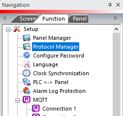
— or — - from the Navigation window, click the Function tab, click Setup and then select Protocol Manager.
- From the Protocol Manager window, click the Device name on the tree to the left.
- The Device Setup window opens.
- From the PLC Protocol field, click on the down arrow
 and select Allen-Bradley EtherNet/IP Client (MicroLogix 1100).
When you select a different PLC Protocol than the one currently in use, the warning Message shown below appears.
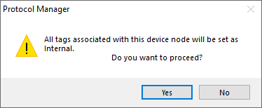
- Click Yes to accept.
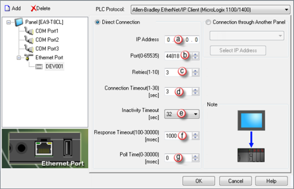
From the Protocol Manager window shown above, configure each field as follows:
PLC Protocol Settings
a. IP Address
The IP Address of the target PLC.(See CPU settings of the Hardware Configuration.)
b. PLC Port (0-65535)
The TCP Port number that you are targeting.
|
|
Note: If you are on the same local network as the Allen-Bradley PLC, you should always use 44818 as the number. Only use a different number if trying to go through a router or if instructed so by your local Network Administrator. |
The destination TCP port number that C-more sends to the GS-EDRV.502 is the standard default. Sometimes this number may need to be adjusted for firewall/router purposes.
c. Retries (0-10)
The C-more panel will send a request to the specified device. If the device does not reply within the specified timeout, the C-more sends the request again. Once the retry count (specified in this field) limit is reached, the C-more panel displays a PLC Timeout error on the screen.
d. Connection Timeout
The amount of time that the panel waits on a reply after a send request.
e. Inactivity Timeout (sec)
This value is sent to the PLC. The PLC holds an open connection for this amount of time. Once the time expires, The PLC releases the connection to free up PLC resources.
The Panel automatically created a new connection when it is ready to request data again.
Only adjust this value if many devices communicate to the PLC and there are situations where there are long delays in requests from the Panel to the PLC (long poll times, screens with only internal objects, etc.).
f. Response Timeout (0-30000) [msec]
The amount of time (in milliseconds) the panel waits on a reply after a send request.
Once the response timer expires, The PLC retries.
g. Poll Time (0-30000) [msec]
The amount of time (in milliseconds) that the panel waits in between each request.
Connection Through Another Panel
You can configure this protocol for any PLC supported by C-more panels.
You can connect a C-more panel to other C-more panels on your network via an ethernet connection. This type of connection is also known as a Pass Through Connection.
Go to Connection Through Another Panel (Pass-Through) to learn more about Pass Through and using Connection Through Another Panel.
Troubleshooting the PLC to Panel Connection
Network Communication Errors Troubleshooting
If your network returns communication errors:
Test the basic network setup
- Transfer a new C-more project with Panel Manager settings that match the PLC port settings and a single Numeric Display object addressed to N7:0.
- Ensure that the PLC port settings are correct by verification with that PLC programming software.
- Power cycle the PLC, then the C-more panel.
- If communication errors persist, power cycle the C-more panel, then the PLC.
